10.03
3.9 Fine adjustment and optimization
3-71
Siemens AG, 2003. All rights reserved
SINUMERIK 840D/SIMODRIVE 611 digital, HLA Module (FBHLA) - 10.03 Edition
Relevant machine data:
MD 5406: SPEEDCTRL_GAIN_A (P gain of velocity controller A)
MD 5407: SPEEDCTRL_GAIN (P gain of velocity controller)
MD 5408: SPEEDCTRL_GAIN_B (P gain of velocity controller B)
The theoretical characteristic data of the valve and cylinder are used to calcu-
late a suggested P gain value. The positive feedback area (MD 5406...MD 5408
<0) is included in the calculation to damp the drive system.
The adjustment to real conditions on the machine (special damping require-
ments) should be made according to the following criteria:
1. P component must be as positive as possible.
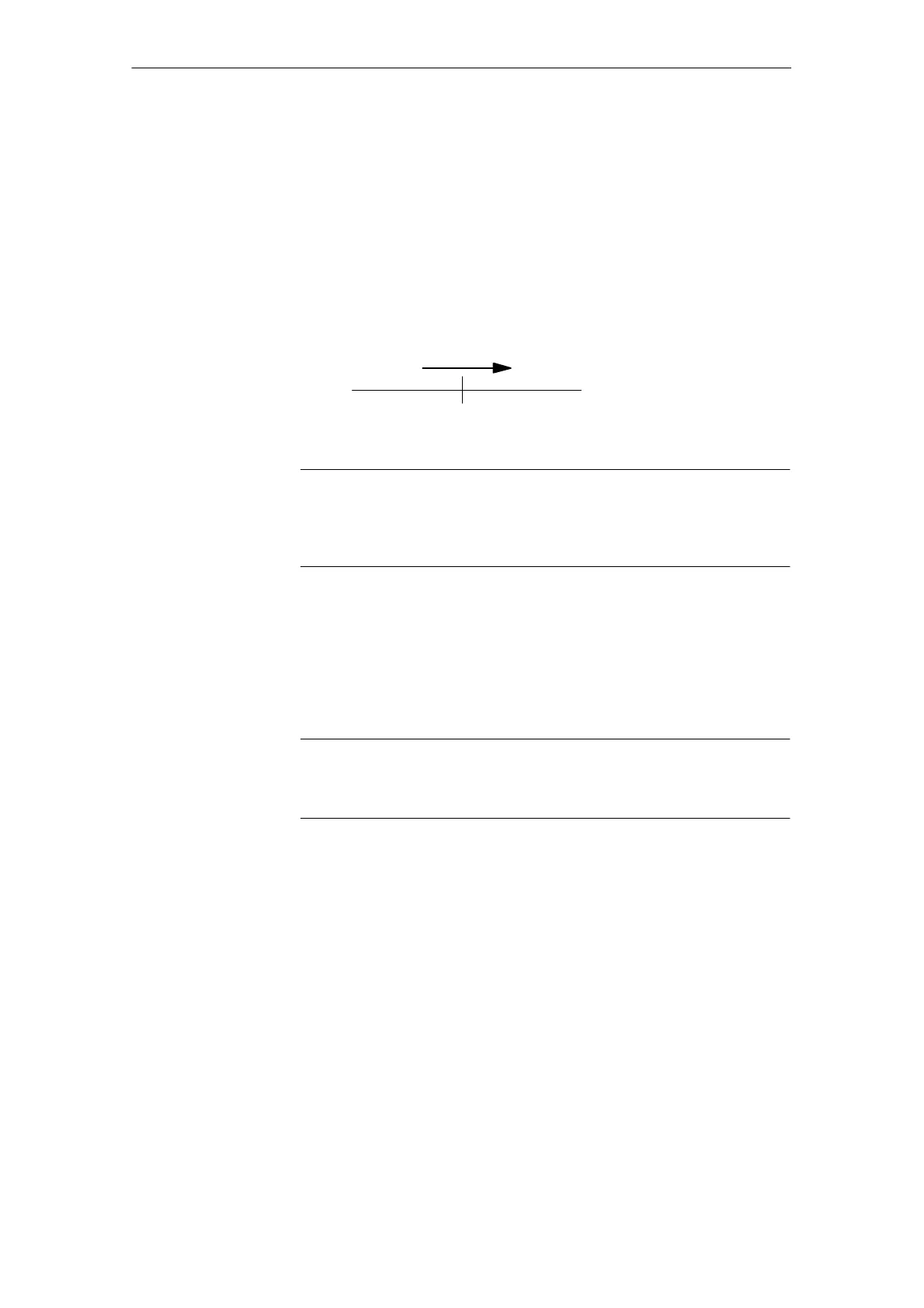
Optimization direction
0< 0 > 0
MD 5406
MD 5407
MD 5408
2. The acceptable overshoot behavior represents the upper limit for the setting.
Note
P<0 (positive feedback) may be necessary to achieve the required damping
behavior. However, this setting will degrade the control quality. Friction in
particular causes prolonged settling times.
Threshold values (typical):
S f
P>0
S f
P<0, or around zero
S f
P>0
(f
...f
see section 3.9.5 point 1...3)
Note
The P gain is indicated as a % of MD 5435: CONTROLLED_SYSTEM_GAIN.
P=-100% compensates the feedforward control.
Relevant machine data:
MD 5431: SPEEDCTRL_DIFF_TIME_A (derivative-action time T
V
of velocity
controller A)
MD 5432: SPEEDCTRL_DIFF_TIME (derivative-action time T
V
of velocity
controller)
MD 5433: SPEEDCTRL_DIFF_TIME_B (derivative-action time T
V
of velocity
controller B)
MD 5430: SPEEDCTRL_PT1_TIME (velocity controller smoothing time
constant)
The positive phase displacement of the derivative term can be used to actively
damp the controlled system for f
type.
The derivative-action time constant/corner frequency parameters must be set to
values higher than the minimum natural frequency of valve and drive.
Optimization of
controller
P component
Optimization of
controller
D component
02.99
 Loading...


