EasyManuals Logo

Siemens Sinumerik 840D Series Function Manual

Siemens Sinumerik 840D Series
288 pages
To Next Page IconTo Next Page
To Previous Page IconTo Previous Page
Page #81 background imageLoading...
Page #81 background image
10.03
3.11 Start-up functions
3-81
Siemens AG, 2003. All rights reserved
SINUMERIK 840D/SIMODRIVE 611 digital, HLA Module (FBHLA) - 10.03 Edition
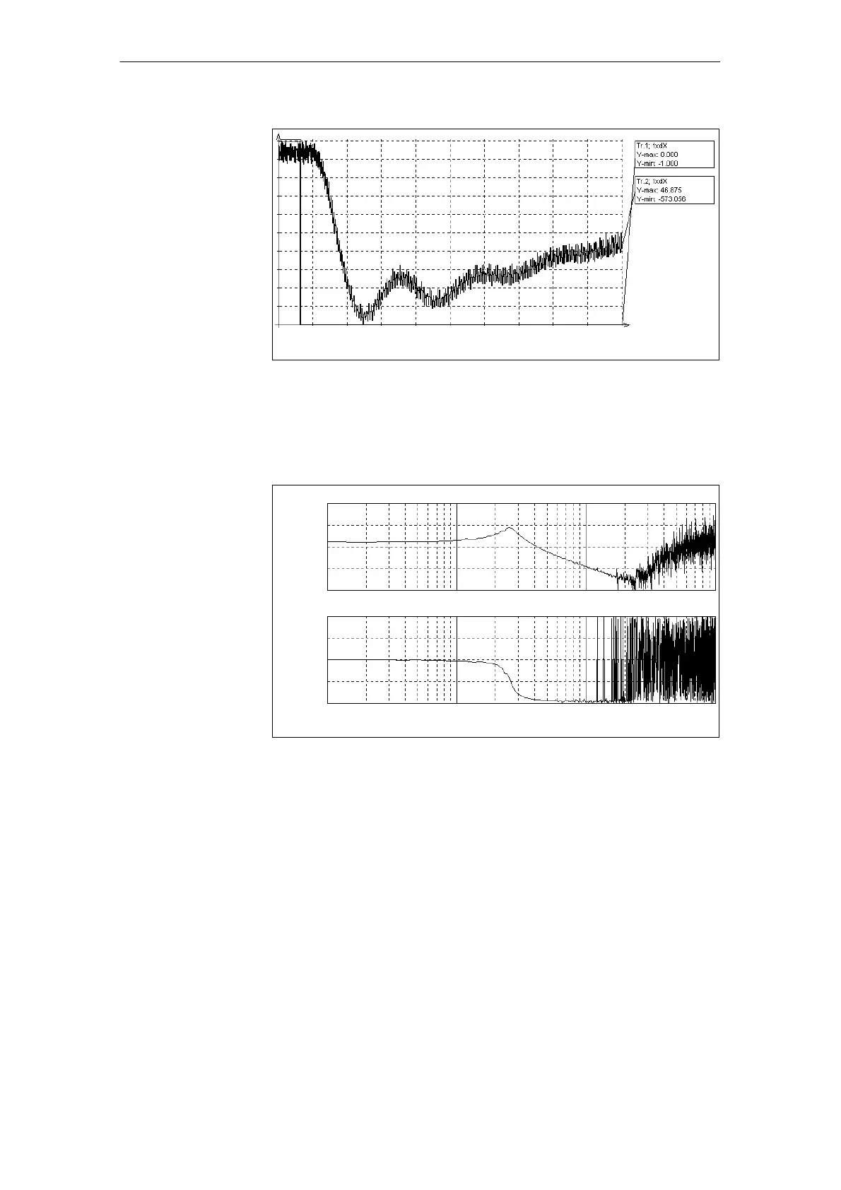
0.100 100.000t [ms]
Fig. 3-32 Timing of disturbance step change, integral branch of velocity controller
deactivated
Trace 1: valve spool setpoint
Trace 2: Actual velocity value
90.000
10.000
180.000
-180.000
Ampl.
[dB]
Phase
[degrees]
1.000 1000.000log [Hz]
Fig. 3-33 Oscillogram showing velocity controlled system v
act
/Q
act
Note: Phase crossover -90 degrees essentially characterizes the
cylinder natural frequency
3 Startup
02.99

Table of Contents

Other manuals for Siemens Sinumerik 840D Series

Questions and Answers:

Question and Answer IconNeed help?

Do you have a question about the Siemens Sinumerik 840D Series and is the answer not in the manual?

Siemens Sinumerik 840D Series Specifications

General IconGeneral
AxesUp to 31 axes
Power Supply24 V DC
Control TypeCNC
InterfaceEthernet, PROFIBUS
DisplayTFT color display
PLCIntegrated PLC (programmable logic controller)
Operating Temperature0°C to 45°C
Relative HumidityUp to 95% (non-condensing)
Max. Number of ChannelsUp to 10 channels

Related product manuals