10.03
3.11 Start-up functions
3-85
Siemens AG, 2003. All rights reserved
SINUMERIK 840D/SIMODRIVE 611 digital, HLA Module (FBHLA) - 10.03 Edition
For an explanation of how to use the function generator, please refer to
References: /FBA/, DD2 “Speed control loop”
/SHM/, SIMODRIVE 611 “Manual for MCU 172A”
An overview of the function generator functions provided for HLA is given below,
with only the purely hydraulic-specific functionality for HLA described in detail.
Table 3-8 Signal (operating mode) for valve spool setpoint
Trigger Signal type
Valve spool setpoint in velocity controller cycle, valve
control loop closed, velocity control loop open
Square-wave
Table 3-9 Signal (operating mode) for valve spool setpoint parameter settings
Parameters Physical unit
Signal type: Square-wave
Amplitude V
Period ms
Pulse width ms
Offset V
limitation V
t [ms]
1.9890
2.0510
200.0000
-2.0260
-2.0610
V
V
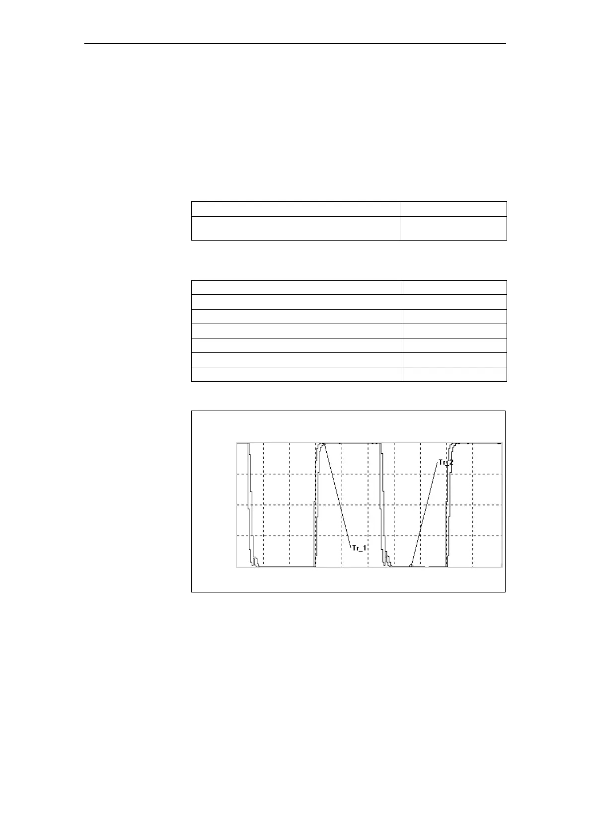
Tr. 1: Valve stroke setpoint
Tr. 2: Actual valve stroke
0.0000
Fig. 3-38 Servo trace of actual valve value with square-wave signal type to valve
setpoint
Valve spool
setpoint
(manipulated
voltage)
02.99
 Loading...


