EasyManuals Logo

Siemens Sinumerik 840D Series Function Manual

Siemens Sinumerik 840D Series
288 pages
To Next Page IconTo Next Page
To Previous Page IconTo Previous Page
Page #86 background imageLoading...
Page #86 background image
10.03
3.11 Start-up functions
3-86
Siemens AG, 2003. All rights reserved
SINUMERIK 840D/SIMODRIVE 611 digital, HLA Module (FBHLA) - 10.03 Edition
Table 3-10 Signal (operating mode) for velocity setpoint
Trigger Signal type
Velocity setpoint in velocity controller cycle, valve control
loop closed, velocity control loop closed
Square-wave
Table 3-11 Signal (operating mode) for velocity setpoint parameter settings
Parameters Physical unit
Signal type: Square-wave
Amplitude (linear axis) mm/min | inch/min
Period ms
Pulse width ms
Offset (linear axis) mm/min | inch/min
Limitation (linear axis) mm/min | inch/min
Note
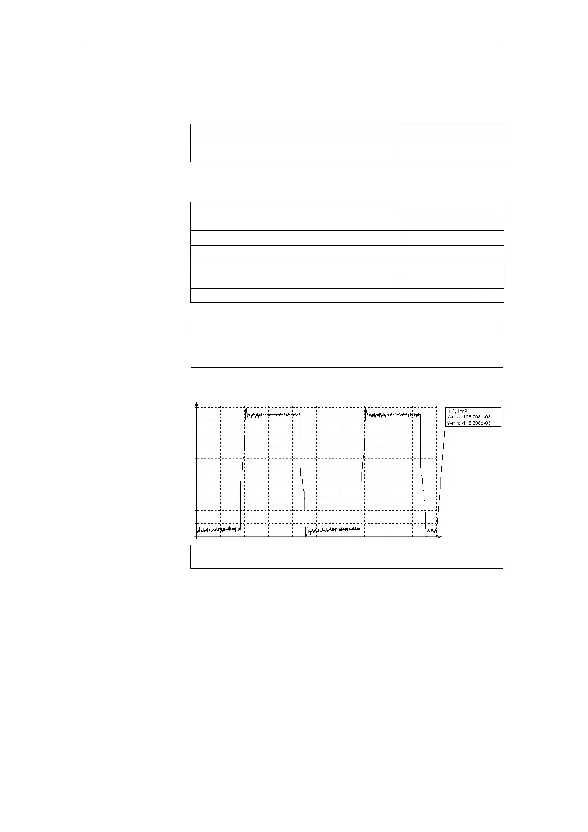
The following diagram was created using a servo trace.
t [ms]
0.000 2.000e+03
Fig. 3-39 Servo trace of actual velocity with square-wave signal type to velocity setpoint
Amplitude: 100 mm/min.
Velocity setpoint
3 Startup
02.99

Table of Contents

Other manuals for Siemens Sinumerik 840D Series

Questions and Answers:

Question and Answer IconNeed help?

Do you have a question about the Siemens Sinumerik 840D Series and is the answer not in the manual?

Siemens Sinumerik 840D Series Specifications

General IconGeneral
AxesUp to 31 axes
Power Supply24 V DC
Control TypeCNC
InterfaceEthernet, PROFIBUS
DisplayTFT color display
PLCIntegrated PLC (programmable logic controller)
Operating Temperature0°C to 45°C
Relative HumidityUp to 95% (non-condensing)
Max. Number of ChannelsUp to 10 channels

Related product manuals