Configuration
5-38 7SJ62 Manual
C53000-G1140-C121-1
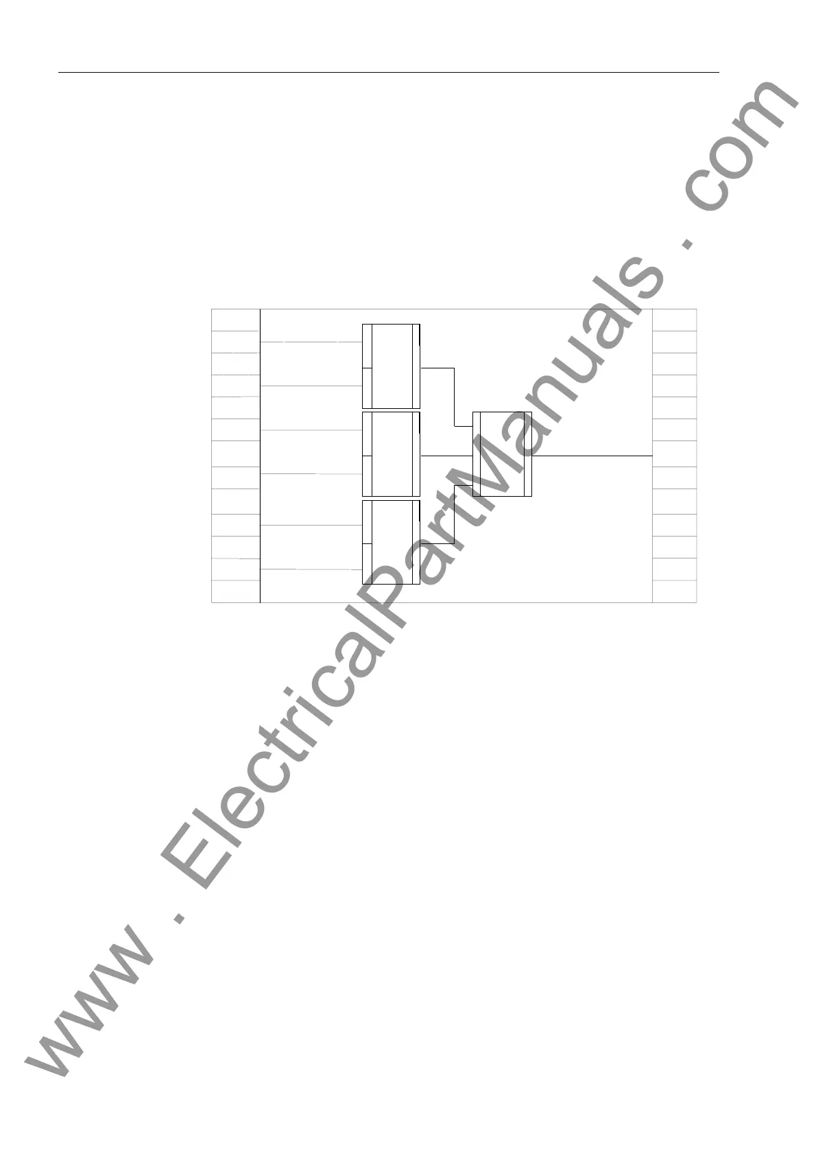
• A lower limit setpoint value (IL<) is linked with the setpoint inputs of each of three
limit sensor functions.
• The limit value function outputs are passed on to the OR gate.
• The output of the OR gate is connected to the right border column at annunciation
“²DODUP”.
The limit value message is triggered when the preset limit value is below the setpoint
(low current) in at least one of the three phases. The hysteresis of the limit values is
fixed and need not be entered (5 % of set point plus 0.5 % absolute).
Figure 5-39 Under-Current Monitoring as an Example of User Defined Measurement Value
Processing
Example 2:
Isolation Switch
Interlocking
Interlocking logic (see Figure 5-40) is to be implemented for the operation of an isolat-
ing switch using function key 4. The user must take the switch position indications of
the corresponding isolation switch and the grounding switch into account. The CLOSE
and TRIP indications from the auxiliary contacts of each switch are used.
• Function modules NOR (2 required), XOR, and AND are taken from the library and
copied into the working page.
• The inputs of the AND gate are increased to 7.
• The CLOSE indications from the circuit breaker (CB) and from the grounding switch
(GS) are supplied to the inputs of the NOR functions.
• The OPEN indications from the circuit breaker (CB) and from the grounding switch
(GS) are supplied to the inputs of the AND function.
• The switch position indications from the disconnect switch (IS) are linked to the in-
puts of the XOR function.
• The outputs of the NOR and XOR gates are connected to the inputs of the AND
function.
• Function key 4 is linked with an input of the AND function.
• The output of the AND gate is linked to the right border column at the command
“Disconnector Close”.
FM:
Lower
Setpoint
VolLimit
37-1
alarm OUT
Measurement
Ia
FM:
Vol
Annunciation BO
Limit
FM:
Vol
Annunciation BO
Limit
Lower
Setpoint
Lower
Setpoint
FM:
Set points
37-1
Measurement
Ib
Set points
37-1
Set points
37-1
Measurement
Ic
Annunciation BO
or
www . ElectricalPartManuals . com

 Loading...


