Configuration
5-397SJ62 Manual
C53000-G1140-C121-1
Figure 5-40 Interlocking an Disconnect Switch as an Example of a User Defined Interlock
Protective Function
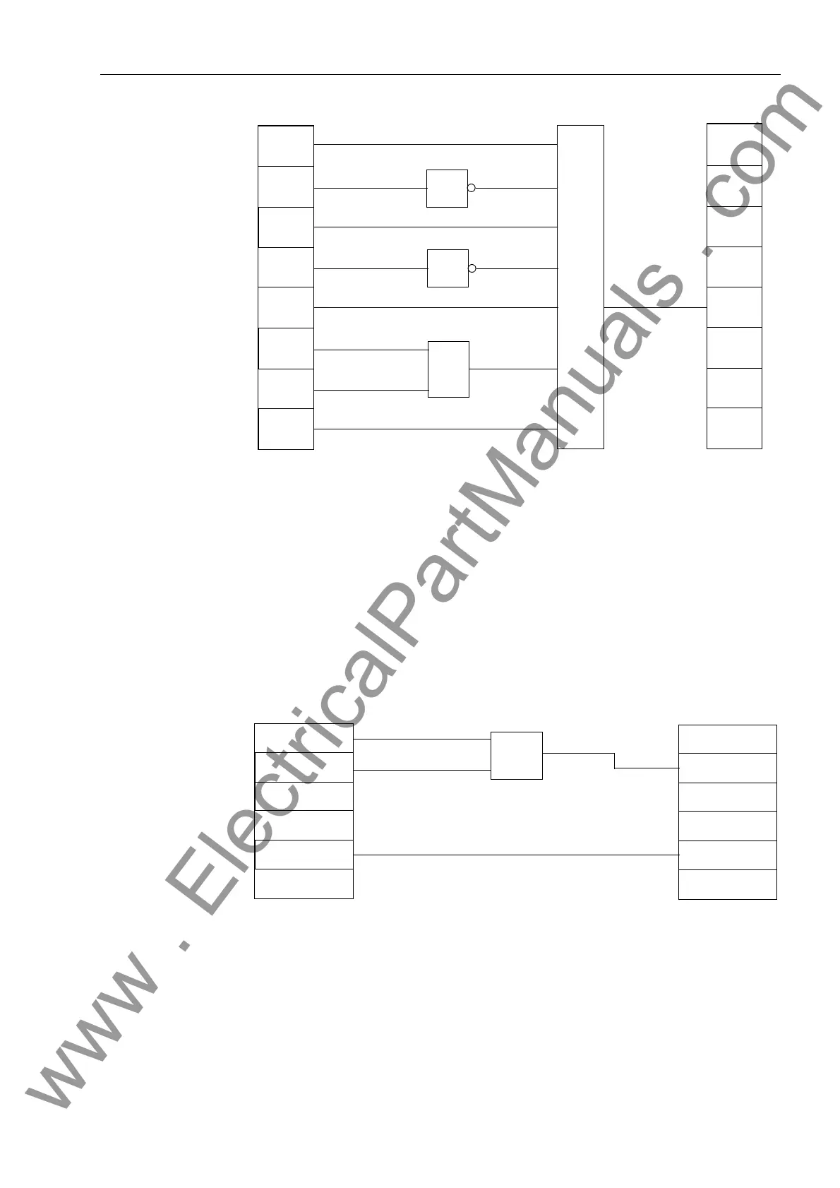
Example 3 (PLC1):
Additional Logic
By using slow PLC processing, an additional, event-driven logic condition may be con-
structed which delivers indications regarding facility operating status. These indica-
tions may be passed externally via LEDs or relays, or used as input signals for further
logical links. In the example (see Diagram 5-41), the output information indication from
the circuit breaker interlocking logic (CB TRIP) and a joint indication from all protective
element trip signals (Protection TRIP) are linked to a new “&LUFXLW%UHDNHU7ULS”
message. Furthermore, the single point indication (SP) 7HVW2SHU, which may be
coupled via a binary input, is coupled with an internal reusable “7HVWRSHU” mes-
sage.
Figure 5-41 Additional Logic as an Example for a PLC_1 Event-Driven Logic Condi-
tion
&
CB is
CB is
GS is
GS is
IS is
IS is
Door
is CLOSED
Disconnector
or
or
= 1
Function
Key 4
Close
CLOSED
OPEN
CLOSED
OPEN
CLOSED
OPEN
Test Oper.
or
CB TRIP
>Test Oper.
Circuit Breaker
Protection TRIP
has tripped
www . ElectricalPartManuals . com

 Loading...


