Functions
6-757SJ62 Manual
C53000-G1140-C121-1
be in the opposite direction (reverse direction). This method it typically used to deter-
mine the direction of ground connections in an ungrounded
system.
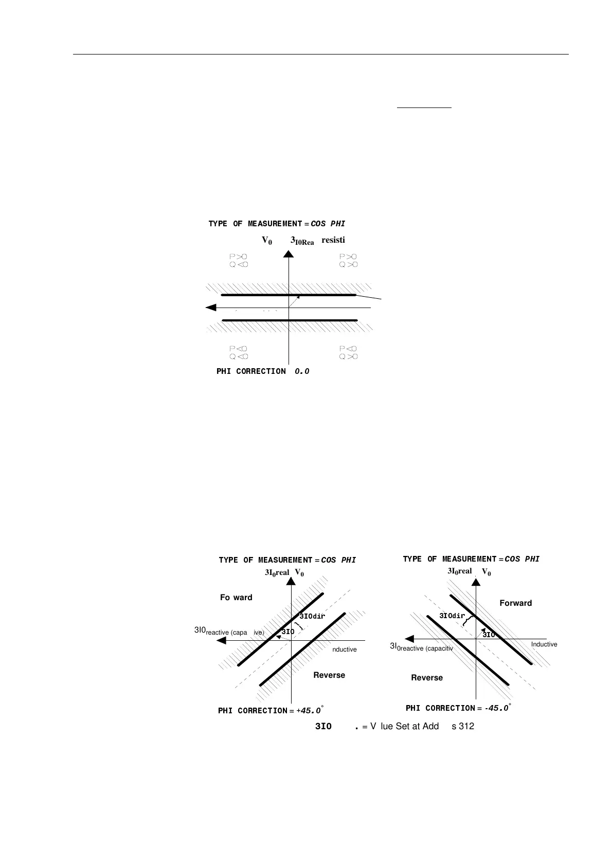
Curves Figure 6-32 illustrates the directional characteristic of the sensitive ground fault detec-
tion function using a complex vector diagram in which the displacement voltage V
0
is
the reference magnitude. Address is set to &263+,, therefore, the current
3I
0real
is calculated and compared with the value set at address
.
The directional
limit lines are perpendicular to 3I
0real
.
Figure 6-32 Directional Lines for cos-ϕ Measurement
Measurement The directional limit lines may be rotated by a correction angle set at address
3+,&255(&7,21 up to ±45°. Therefore, it is possible to increase sensitivity in the
resistive-inductive range with a rotation of –45°, or in the resistive-capacitive range
with a rotation of +45° (see Figure 6-33). If the sin-ϕ method is used, the directional
limit lines would be rotated by 90°.
If address 3+,&255(&7,21 is set other than 0°, the angle of the directional
limit line is determined from the sum of the real and reactive components of zero se-
quence power.
Figure 6-33 Directional Lines for cos-ϕ Measurement
0(66$57 &263+,
3+,.255(.785
U
E
IE E G E R .
{
I
EE
3I
0
dir. = Value Set at Address 3123
7<3(2)0($685(0(17
=
&263+,
V
0
3
I0Real
(resistive)
Forward
Reverse
3I
0reactive (capacitive)
3I
0dir
3I
0
3+,&255(&7,21
=
O
Setting
I
EEw
U
E
I
EEb (
kapazi ti v)
induktiv
0(66$57
cos PHI
3+,.255(.785
I
EE
}
GER
IEE
}
I
EEw
U
E
I
EEb (
kapazi t i v)
indukti
0(66$57 FRV3+,
3+,.255(.785
IEE
GER
IEE
IEE GER = Einstellwert
)5(,*$%(
5,&+7
7<3(2)0($685(0(17
=
&263+,
7<3(2)0($685(0(17
=
&263+,
3+,&255(&7,21
=
°
3+,&255(&7,21
=
°
Forward
Reverse
Forward
Reverse
3I
0
real
3I
0
real
V
0
V
0
3I0
reactive (capacitive)
3I
0reactive (capacitive)
Inductive
Inductive
,GLU
,
,GLU
,
,GLU = Value Set at Address 3123
www . ElectricalPartManuals . com

 Loading...


