Routine Checks and Maintenance
9-117SJ62 Manual
C53000-G1140-C121-1
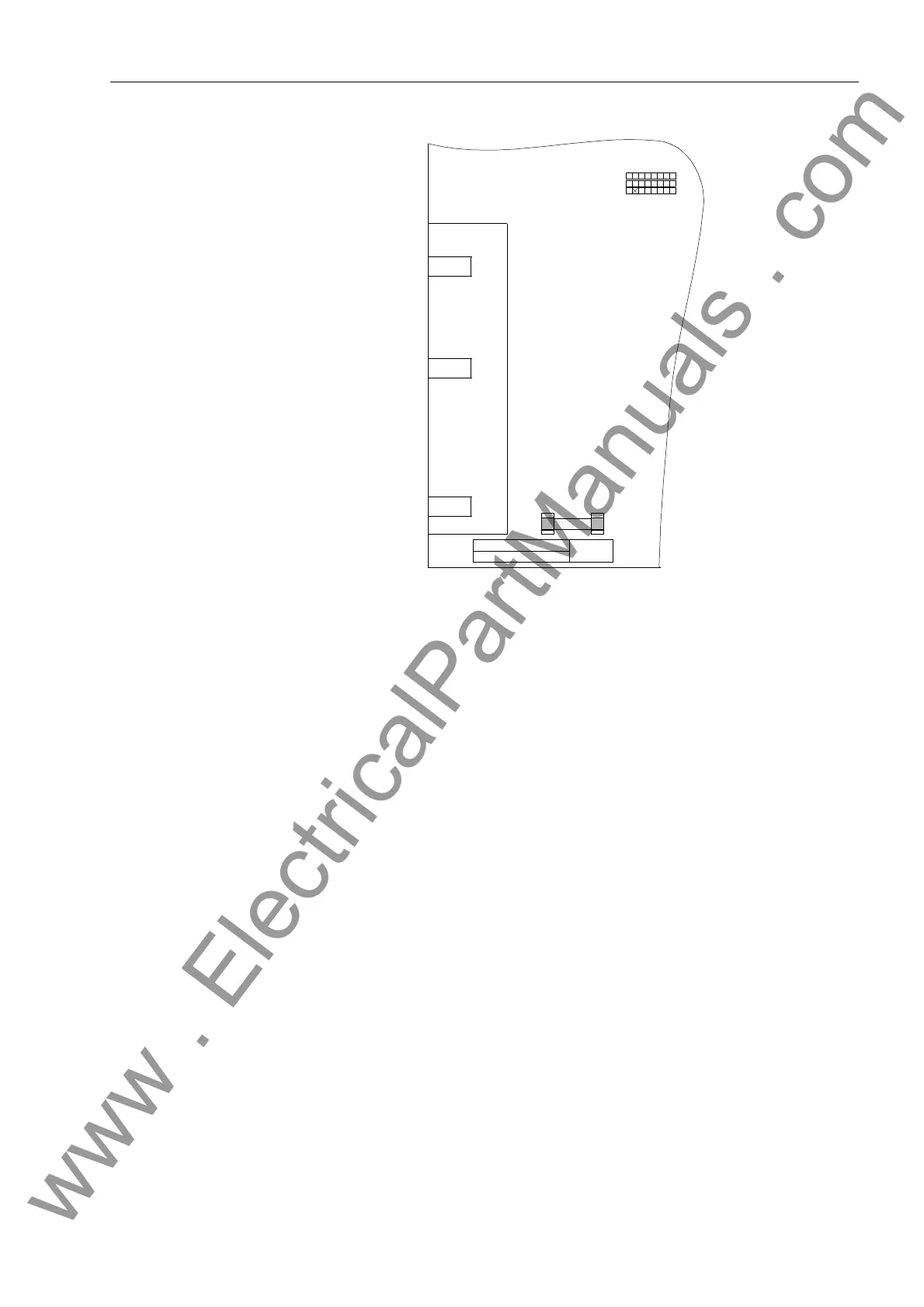
Figure 9-5 Power Supply Fuse on the Processor Printed Circuit Board CPU
o Install a new fuse in the holder.
o Carefully install the CPU board in the case. The position for the board is shown in Fig-
ure 9-1.
For the version of the device designed for surface-mounting, use the metal lever to in-
sert the CPU board. The installation is then easier.
Reassembling the
Device
To reassemble the device:
o By first attaching to the I/O board, connect the ribbon-cable between the I/O board and
the CPU board. Be especially careful not to bend any of the connector pins! Do not
use force! Be sure the connectors latch.
o Connect the ribbon-cable between the CPU board and the front panel. Be especially
careful not to bend any of the connector pins! Do not use force! Be sure the plug con-
nectors latch.
For the surface-mounted device, first connect the ribbon-cable from the 68-pin con-
nector on the back of the device. Then attach connector X16 under the D-subminiature
port on the CPU board. Make sure all connections are done properly.
o Carefully replace the front panel being mindful of the ribbon-cables. Fasten the front
panel to the case with the four screws.
o Replace the four corner covers.
For the surface mount version the following steps are not applicable:
o Align and fix the rear interfaces again.
F1
B21 B22 B23 B25 B26 B27 T 2.0/250 G
B20 B24
-B20-
-B21-
C53207-A322-B22-
-B23-
-B24-
-B25-
-B26-
-B27-
123
www . ElectricalPartManuals . com

 Loading...


