The SINAUT Configuration Tool
6.6 TD7onTIM
TIM DNP3
System Manual, 06/2014, C79000-G8976-C253-03
229
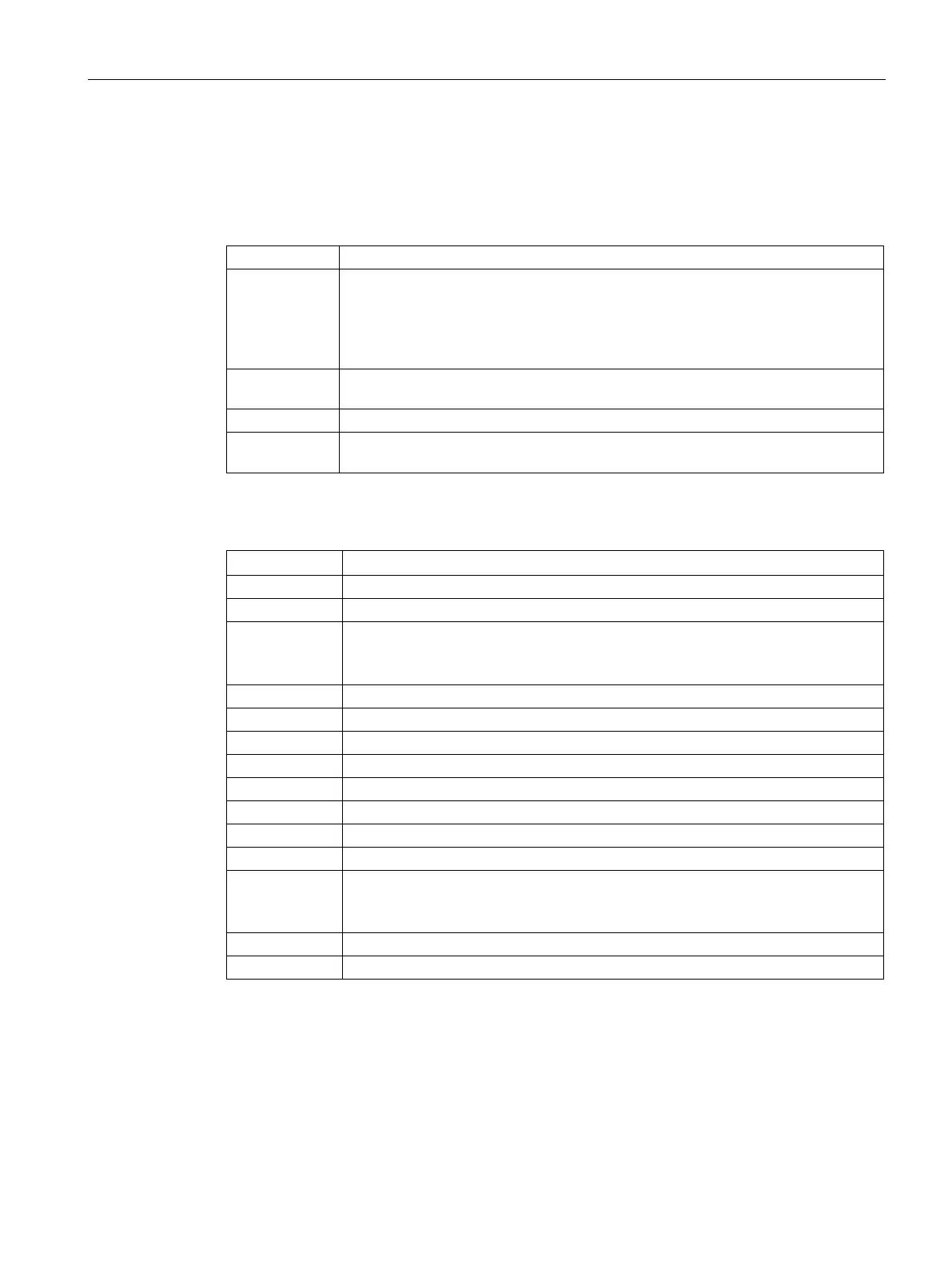
cifying the data type, you specify the data type with which the data is
transferred from the S7 CPU to the MODBUS slaves. The drop
-down list
offers the following data types for the three memory areas:
BOOL, BYTE, CHAR, WORD, DWORD, INT, DINT, REAL
Number of double words included in the array (maximum 100).
Specifies the DB number in the CPU if the data block memory area (DB) was
selected
Input field for the byte number in the selected memory area. For data types
involving
more than one byte (WORD, DWORD), the least significant byte
number must be entered as in STEP 7.
Here, the register address on the MODBUS slave to which the data will be written is
specified.
Register
address:
Specifies the register address.
You will find the permitted address ranges in the documentation of your MODBUS
Range of
0...65535
Function code: Specifies the MODBUS data type. The following MODBUS data types are available:
• Write single coil
(write 1 value, 1 bit)
• Write multiple coils
(write multiple values,1 bit)
• Write single register
(write 1 parameter,16 bits)
• Write multiple registers
(write multiple parameters,16 bits)
Default setting:
• MODBUS output
– Function code: Write single register
• S7 CPU input address
– Data type: WORD
– Number: 1
 Loading...