SDS1000X-E User Manual
84
I2C Trigger and Serial Decode
Please in order of “Setup for I2C Signals”, “I2C Trigger” and “I2C Serial Decode” to
trigger and decode the signals.
Setup for I2C Signals
Setting the I2C (Inter-IC bus) signal includes two steps: connecting the serial data signal
(SDA) and serial clock signal (SCK) to oscilloscope, specifying the threshold voltage of
each input signal.
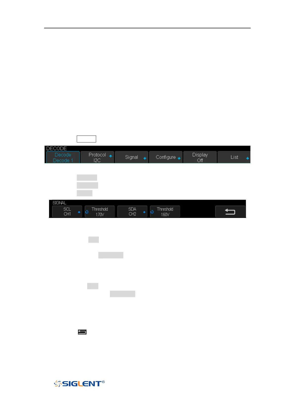
1. Press the Decode key to enter the DECODE function menu as Figure 34 shows.
Figure 39 I2C DECODE Menu
2. Press the Decode softkey and select the desired slot (Decode1 or Decode2).
3. Press the Protocol softkey and then select I2C by turning Universal Knob.
4. Press the Signal softkey to enter the SIGNAL menu as Figure 35 shows.
Figure 40 I2C SIGNALLE Menu
5. Set SCL (I2C’s clock signal):
a. Press the SCL softkey to select the channel that is connected to the I2C clock
signal.
b. Press the first Threshold softkey to set the I2C clock signal’s threshold voltage
level by Universal Knob. The threshold voltage level is for decoding, and it will
be regard as the trigger voltage level when set the trigger type to serial.
6. Set SDA (I2C’s data signal):
a. Press the SDA to select the channel that is connected to the I2C data signal.
b. Press the second Threshold softkey to set the I2C data signal’s threshold
voltage level by Universal Knob. The threshold voltage level is for decoding, and
it will be regard as the trigger voltage level when set the trigger type to serial.
(Tips: SDA should keep stable during the whole high clock cycle, otherwise it will be
interpreted as a start or stop condition (data transitioning while the clock is high))
7. Press the softkey to return previous menu.