6-2
4007ES Panel Programmer Manual (579-1167)
Editing Standard Component Properties, Continued
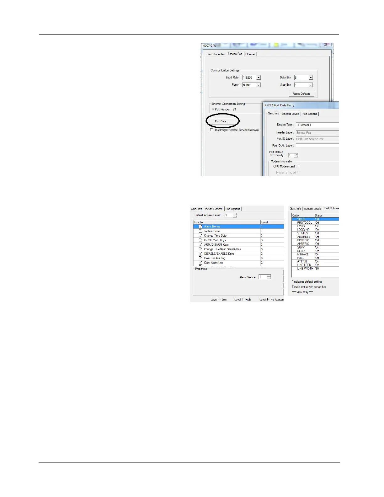
Editing the CPU 3. Click the Gen. Info tab. Enter the
information requested. Click on
Apply and then OK to confirm the
selection (Figure 6-1).
• Device Type: For a CPU card
service port, this field is
permanently set to
COMMAND.
• Header Label: This field
specifies the first line of banner
text that appears at the top of the
CRT screen.
• Port ID Label: This field
specifies the second line of
banner text that appears at the
top of the CRT screen. It is
typically used to designate the
port connection. For example,
“Port 2, Command Center.”
Figure 6-1. 4007 CPU - Gen Info Tab
• Port Default SET Priority CPU Card Only: This is the system priority level assigned to
commands issued from the service port. The range is 2 to 15 and the default is 9.
4. Cl
ick on the Access Level tab
in the RS232 Port Data Entry
window (Figure 6-2). This tab
allows you to set the access
level for the various system
operations that can be carried
out via the service port.To set
an access level for one of the
service port operations, scroll
through the list of functions
and highlight the function. Use
this control to associate an
access level with the function.
Click on Apply and then OK
to confirm the selection.
Figure 6-2. 4007 CPU Access Levels and Port Options
Note: These access levels apply only to actions performed through the service port, not for operations
made at the panel display.
5. Click on the Port Options tab in the RS232 Port Data Entry window. This tab contains
options that apply to the way data appears on the display connected to the service port.
These are read-only fields. Click OK to return to the Service Port tab.
6. Click in the TrueInsight Remote Service Gateway box to enable the use of the Remote
Service Gateway.
To edit the Ethernet tab:
1. Click the Use Default box or enter the name that the building network has attributed to the
FACP.
2. Click on Apply to confirm the selection.