15
Pneumatic system adjustements
In order to have air flow inside the pneumatic system, act on the isolator (1) and then turn the
knob of the regulator (2) checking the pressure gauge (4) to control the pressure level reached.
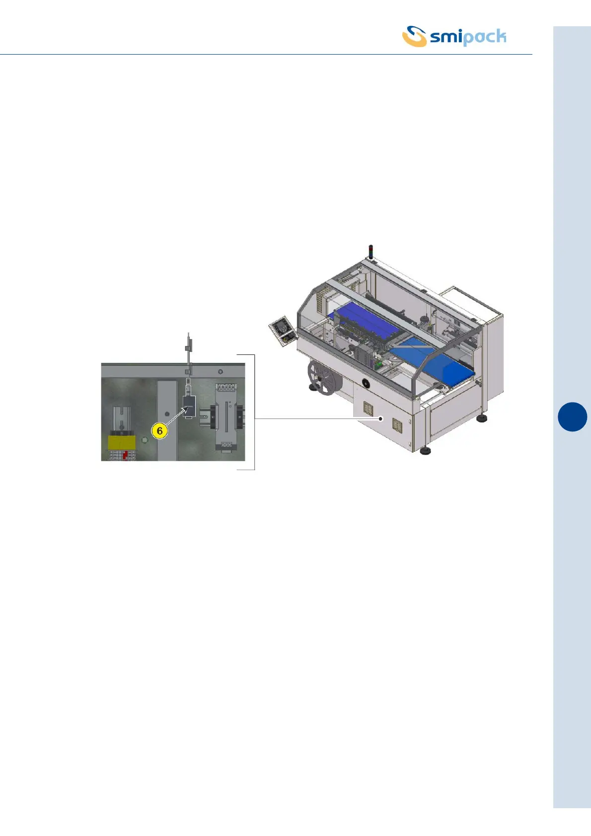
The machine also has a pressure switch installed on it located inside the electrical control
board which, in the event of an air shortage inside the system, indicates this anomaly on the
operator panel. Upon delivery the machine is calibrated to intervene when pressure drops
below the threshold of 4 bar (if you wish to modify calibration, consult the specific user manual
of the pressure switch). For connection, insert the air source in the infeed fitting (3) for a Ø10
mm tube.
The data for the pneumatic system are listed here below:
- Operating pressure: 6 bar
- Maximum impurity degree : 40 µm (solid particles), 0,5 PPM (liquid particles)