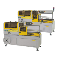
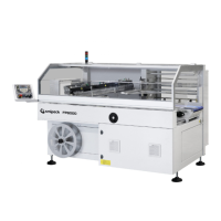
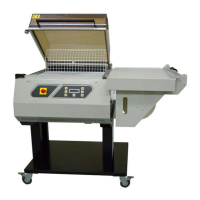
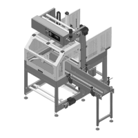
3 - Description of the machine
14
Electrical installation data
Install a circuit breaker on the machine power supply line which supports the values indicated
in the table.
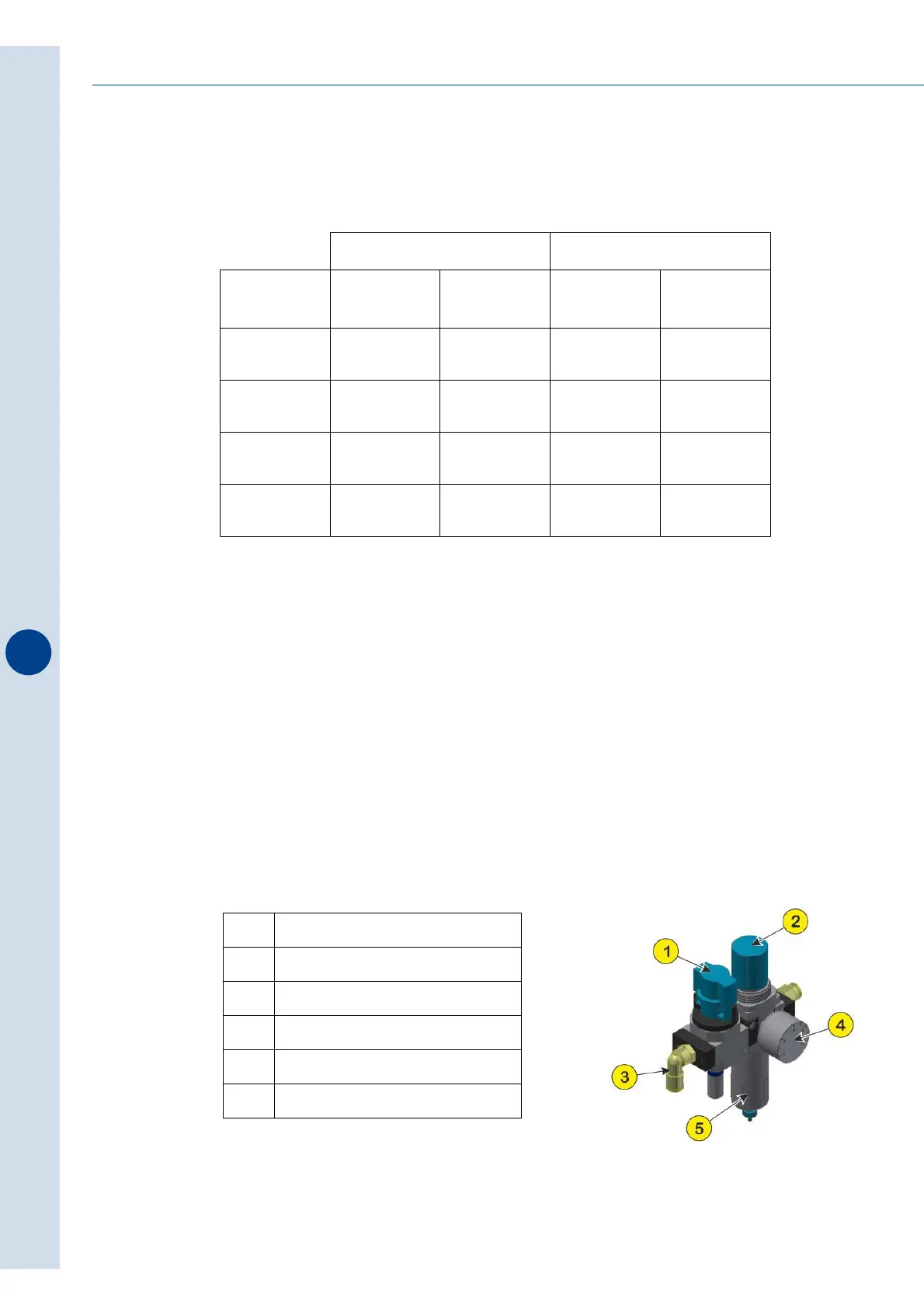
3.5 Pneumatic system (applicable only for optional systems)
The list of pneumatic components and their wiring diagrams are attached to this manual
(SPARE PARTS LIST section).
It is very important that the compressed aire required for the operation of the components is
purified. Indeed the presence of impurities contained in the air coming from the compressor
and condensed humidity favour the wear of the seals and of the relative sliding surfaces
compromising the durability of the pneumatic components.
For air pressure regulation inside the pneumatic system, the machine is provided with an
appropriate module equipped with a lockable isolator, a pressure regulator, a filter and a
pressure gauge.
FP6000 - FP6000CS FP8000CS
Nominal
voltage
380÷415 V
(3PH+N+PE)
220÷240 V
(3PH+PE)
380÷415 V
(3PH+N+PE)
220÷240 V
(3PH+PE)
Nominal
frequency
50÷60 Hz 50÷60 Hz 50÷60 Hz 50÷60 Hz
Nominal
power
3350 W 3350 W 3950 W 3950 W
Nominal
current
14,5 A 14,5 A 17,5 A 17,5 A
Cross-section
of cable
2,5 mmq 2,5 mmq 2,5 mmq 2,5 mmq
1 Lockable isolator
2 Pressure regulator
3 Ø10 supply
4 Pressure gauge
5 Filter
6 Pressure switch