EasyManuals Logo

Solid State Logic Matrix 2 User Manual

Solid State Logic Matrix 2
170 pages
To Next Page IconTo Next Page
To Previous Page IconTo Previous Page
Page #37 background imageLoading...
Page #37 background image
Chapter 3 Analogue Signal Flow
In this chapter we will be examining the analogue side of Matrix, focusing on its extensive routing capabilities and
e
xamining the unique Matrix automation facility. We will also cover the SSL soft keys, which affect both analogue and
DAW control domains.
Introduction to Focus Modes
Matrix combines two distinct modes of operation in one control surface, providing control of both the analogue
signals and the DAW functions associated with the modern recording environment. In order to accomplish this within
a compact space, the console can operate in two ‘Focus’ modes, focusing on either the analogue or DAW control
functions. These modes are called Analogue Focus and DAW Focus.
Focus modes primarily affect the channel faders and their (' and &"" buttons which control the analogue signal
when in Analogue Focus mode, but send control messages to the DAW when in DAW Focus mode. Focus modes
also affect the channel meters which normally meter the analogue signal in Analogue Focus mode but replicate the
DAW track metering in DAW Focus mode. The scribble strip also functions differently in each Focus mode.
It is possible to lock the meters to either the analogue channel or DAW track signals regardless of the
console’s Focus mode. This is done via the Meter menu in the SSL soft keys. See Page 43 for more details.
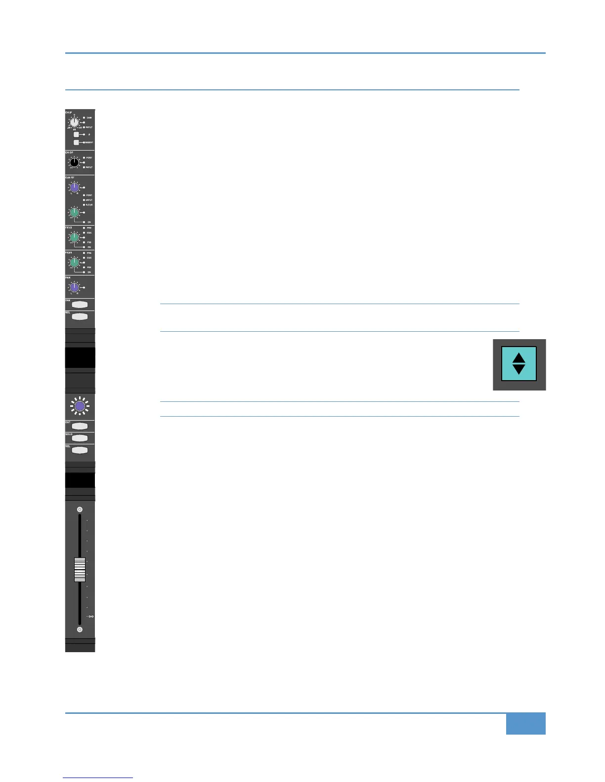
Matrix’s mode is selected and indicated by the large Focus button, located directly underneath the
Master Channel, on the left of the centre section (shown right). Pressing this button swaps between
Focus modes. It is lit to indicate Analogue Focus, and unlit to indicate DAW Focus.
In this chapter, we will be concentrating on Analogue Focus mode, so the Focus button should be lit.
See Page 74 for more on Focus modes.
Operating Principles
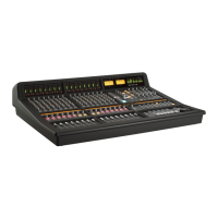
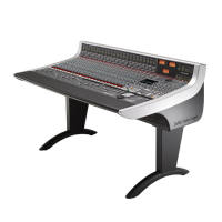
The Matrix control surface is divided into two parts: the 16 channel strips make up the left hand side of the console
while the ‘Centre Section’ (which houses all the out-of-channel controls, along with the Master Channel (see next
page), makes up the right hand side of the console.
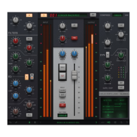
The Matrix channel strip (shown left) is split into two sections: the top section, from the channel metering down to
the digital scribble strip, controls most of the analogue side of the desk (signal routing and source selection etc), and
we will therefore focus our attention there. The lower section of the channel strip, from below the digital scribble
strip down, is more focused on DAW control. However, this section includes the (' and &"" buttons as well
as the fader, all of which function in both analogue and DAW Focus modes.
iJack iJack
CUT
D
IM
i
n
22
62 811
0
0
1
1
2
2
3
3
4
4
5
5
6
6
10
20
30
40
50
5
0
5
10
10
20
30
40
50
5
0
5
10
10
20
30
40
50
5
0
5
10
10
20
30
40
50
5
0
5
10
10
20
30
40
50
5
0
5
10
10
20
30
40
50
5
0
5
10
10
20
30
40
50
5
0
5
10
10
20
30
40
50
5
0
5
10
10
20
30
40
50
5
0
5
10
10
20
30
40
50
5
0
5
10
10
20
30
40
50
5
0
5
10
10
20
30
40
50
5
0
5
10
10
20
30
40
50
5
0
5
10
10
20
30
40
50
5
0
5
10
10
20
30
40
50
5
0
5
10
10
20
30
40
50
5
0
5
10
9
10 11 12 13 14 15 16
1
2345678
1234
5678
23456781 10 11 12 13 14 15 169 MASTER/FOCUS
REC
MON SOLO
MIX
LEFT
RIGHT
REC
MON SOLO
M
IX
SolidStateLogic Matrix
STEF19/05/08
in 2 2
62 811
CUTDIM
ARTIST
20
30
40
50
60
15
10
5
0
10
20
30
40
50
5
0
5
10
ARTIST
t2::TProjec itle
Me etrs
Mon
Auto T
RIPMiscBass
t2:: tprojec i ttl e
metersmonautotripmisc
iJack iJack
CUT
DIM
i
n
22
62 811
0
0
1
1
2
2
3
3
4
4
5
5
6
6
10
20
30
40
50
5
0
5
10
10
20
30
40
50
5
0
5
10
10
20
30
40
50
5
0
5
10
10
20
30
40
50
5
0
5
10
10
20
30
40
50
5
0
5
10
10
20
30
40
50
5
0
5
10
10
20
30
40
50
5
0
5
10
10
20
30
40
50
5
0
5
10
10
20
30
40
50
5
0
5
10
10
20
30
40
50
5
0
5
10
10
20
30
40
50
5
0
5
10
10
20
30
40
50
5
0
5
10
10
20
30
40
50
5
0
5
10
10
20
30
40
50
5
0
5
10
10
20
30
40
50
5
0
5
10
10
20
30
40
50
5
0
5
10
9
10 11 12 13 14 15 16
1
2345678
1234
5678
23456781 10 11 12 13 14 15 169 MASTER/FOCUS
REC
MON SOLO
MIX
LEFT
RIGHT
REC
MON SOLO
M
IX
SolidStateLogic Matrix
STEF19/05/08
in 2 2
62 811
CUTDIM
ARTIST
20
30
40
50
60
15
10
5
0
10
20
30
40
50
5
0
5
10
ARTIST
t2::TProjec itle
Me etrs
Mon
Auto T
RIPMiscBass
t2:: tprojec i ttl e
metersmonautotripmisc
iJack iJack
C
UT
DIM
i
n
22
62 811
0
0
1
1
2
2
3
3
4
4
5
5
6
6
10
20
30
40
50
5
0
5
10
10
20
30
40
50
5
0
5
10
10
20
30
40
50
5
0
5
10
10
20
30
40
50
5
0
5
10
10
20
30
40
50
5
0
5
10
10
20
30
40
50
5
0
5
10
10
20
30
40
50
5
0
5
10
10
20
30
40
50
5
0
5
10
10
20
30
40
50
5
0
5
10
10
20
30
40
50
5
0
5
10
10
20
30
40
50
5
0
5
10
10
20
30
40
50
5
0
5
10
10
20
30
40
50
5
0
5
10
10
20
30
40
50
5
0
5
10
10
20
30
40
50
5
0
5
10
10
20
30
40
50
5
0
5
10
910111213141516123456 7 8
1234
5678
23456781 10 11 12 13 14 15 169 MASTER/FOCUS
REC
M
ON SOLO
MIX
LEFT
RIGHT
REC
MON SOLO
MIX
SolidStateLogic Matrix
STEF19/05/08
in 2 2
62 811
C
UT
D
IM
ARTIST
20
30
40
50
60
15
10
5
0
10
20
30
40
50
5
0
5
10
ARTIST
t2::TProjec itle
Me etrs
Mon
Auto T
RIPMiscBass
t2:: tprojec i ttl e
metersmonautotripmisc
Chapter 3 - Analogue Signal Flow
29
Matrix
2
Owner’s Manual

Table of Contents

Questions and Answers:

Question and Answer IconNeed help?

Do you have a question about the Solid State Logic Matrix 2 and is the answer not in the manual?

Solid State Logic Matrix 2 Specifications

General IconGeneral
BrandSolid State Logic
ModelMatrix 2
CategoryRecording Equipment
LanguageEnglish

Related product manuals