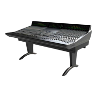
Monitoring
Control Room Monitors
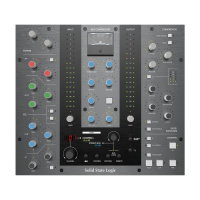
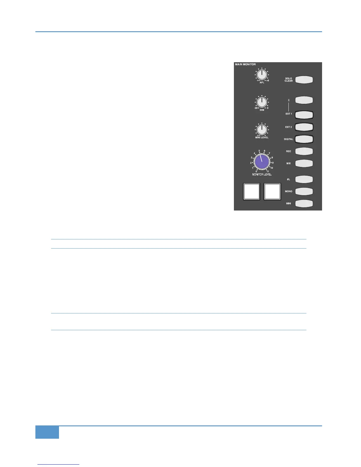
The ! "!'"% area of the Matrix centre section is located to the right of
the Master Channel. The blue pot towards the bottom left of the area is the volume
c
ontrol for the main monitors, and beneath it are two buttons. The left button,
labelled
, immediately reduces the volume of the monitoring. The amount of
gain reduction introduced by the button ranges from –3dB to –30dB and is
controlled by the pot, which is the middle of the three grey pots above the
main volume control. The button to the right of the button, labelled (',
mutes the monitoring. Both the and (' buttons light up to indicate that they
are active.
In the right half of the monitoring area are 10 buttons, which will be described in
ascending order:
Pressing ! swaps the monitoring output from the main monitors to the near-field
monitors. The mini’s have an independent volume control which is the bottom of the
three grey pots, immediately above the main monitor volume control. To return to
hearing the main monitors, press the ! button again. Pressing "!" sends a
left-right summed signal to both speakers. Pressing and holding H inverts the phase
of the left-hand monitor signal. You can monitor the stereo difference (L-R) signal by
pressing H when the "!" button has been selected.
The next five buttons above the H button form the source selector for the monitor
bus. These include the + and % busses along with three external inputs described below: ', +' and +'.
Each buttons lights when active.
Note that while the other buttons light yellow, the % bus lights red in keeping with its colour coding.
Normally these buttons cancel each other (in other words, if you select one source, the previously selected source is automatically
deselected). However, the summing button (
S
), located immediately above the five source selector buttons, removes the
intercancelling feature and instead sums all selected inputs, enabling multiple sources to be monitored simultaneously. Deselecting
the
S
button cancels all monitoring sources and returns the monitoring to intercancelling mode.
The top button in the monitoring area, labelled &""%, clears any &"" or buttons that are active on the desk,
restoring the monitoring source selection in the buttons beneath it. The &""% button lights to indicate that there is a
channel or bus in solo or AFL mode somewhere on the desk, as does the &""light located above the VU meters.
Note that the small light marked &"" beneath the ! "!'"% area displays the solo status of the DAW, not
the analogue channels.
External Monitoring Inputs
Matrix allows up to three external audio sources to feed the monitoring - two analogue and one digital. On the console, these
are labeled ', +' and +'. and their connections are described in Chapter 1. If an MP3 player or iPod is connected
to the iJack socket in the consoles right-hand trim, this signal will replace the +' signal.
After Fade Listen (AFL)
The pot labelled located at the top of the monitoring area sets the main monitoring volume for the stereo AFL function.
Pressing any button on the centre section will replace the current feed to the monitors with the post-level signal (and in the
case of the Matrix channels, post level and pan) associated with that button. Pressing multiple AFLs will sum the selected
signals together. AFLs can be cancelled by pressing the &""% button or by deselecting any active buttons. Centre
section AFLs are unaffected by the solo monitoring soft key options detailed on Page 42.