STEP 11: Inserting Signal Processing into the
Channel
M
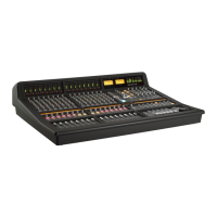
ost mixing desks have signal processing available in the channel. You will probably be aware by now that Matrix
doesn’t, as the outboard and DAW signal processing with which Matrix is designed to work would make in-
channel processing an unnecessary and costly expense. You can, however, insert your outboard signal processing
into the channel using the Insert Matrix in the Matrix Remote:
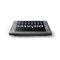
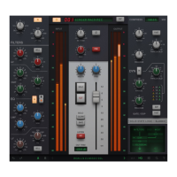
‰ Press channel 16’s
!&%' button, located between the # and "# pots, shown left. Depending
on your setup, the monitoring may now fall silent.
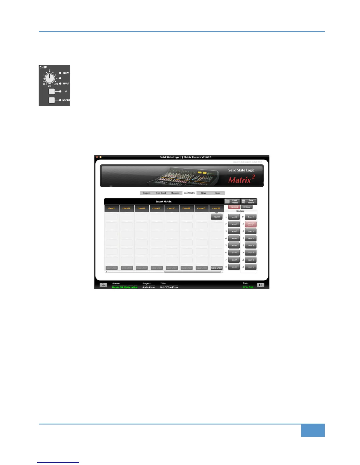
On your computer, run the Matrix Remote and select the =A4@B 0B@8F tab which is the fourth tab from the left. The right
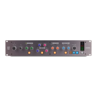
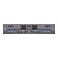
hand-side of the Insert Matrix tab shows you red boxes labelled “=A4@B”, “=A4@B” etc. These boxes represent your analogue
outboard gear you have connected to the Insert Send and Return connections on the back of Matrix. They are known as Devices.
Devices are floating, which means you can freely move them into whichever analogue insert point you like.
‰ Start by renaming each
4D824. You can do this by right-clicking and choosing %4=0<4
‰ Once you have named your devices use the scroll bar at the bottom, to bring 70= into view inside the Insert Matrix
‰ Simply click and drag the device you want and hover over the first available ‘slot’ in channel 16’s column. Release the mouse
click and it will be placed into the insert slot.
The device will then turn red in the
4D824 list to indicate it is in use
For more information regarding the =A4@B 0B@8F, including how to make chains, see Page 67.
Congratulations on completing the Tutorial. You should now be ready to explore some of the more advanced functions of Matrix.
The rest of this manual will fill in the detail wherever you need it.