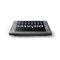
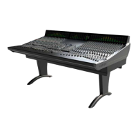
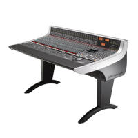
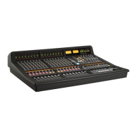
DAW Track Control
A
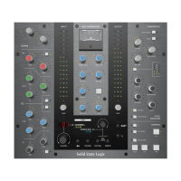
number of the parameters within the tracks of your DAW can be controlled using the lower section of the
Matrix channel strip. The Matrix controls which can be used in this way include:
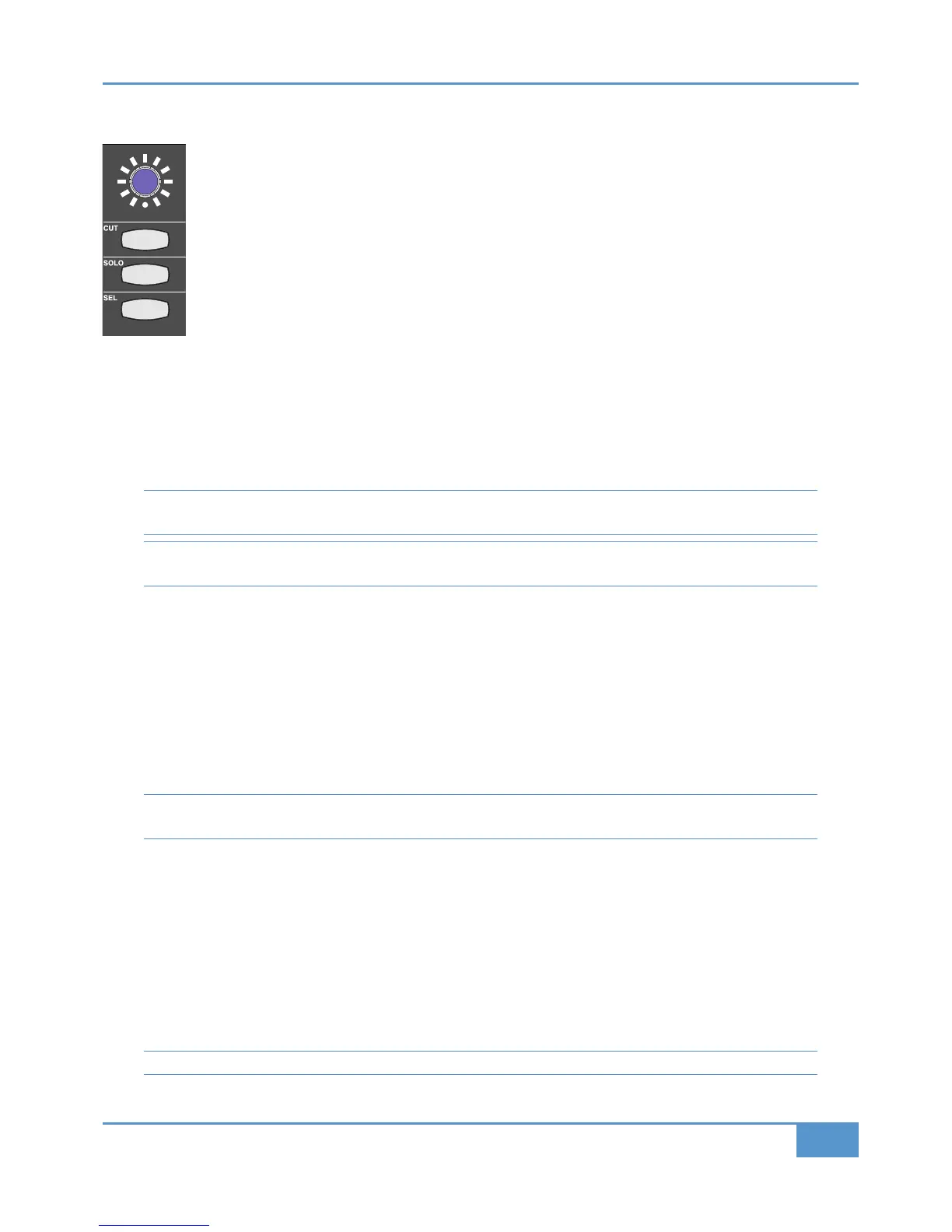
- The blue shaft encoder located below the digital scribble strip, called the V-Pot,
- The momentary switch in the centre of the blue pot, called the V-Sel,
- The
(', &"" and & buttons located beneath the blue pot,
-
The channel fader.
The functions of the V-Pot, V-Sel button and
& button are defined by the protocol-specific assignment soft keys.
Additional options and modes are available via )#"' "and &, buttons described on Pages 76
and 77.
When in DAW Focus mode, the channel (' button mutes the DAW track which that channel is currently controlling, and the
channel &"" button solos the DAW track which that channel is currently controlling. The (' and &"" buttons light when
pressed to show that they are active, just as in Analogue Focus mode. The presence of a solo button within the DAW tracks is
indicated by the (' buttons on all unsoloed tracks flashing, and by the &"" LED to the to the left of the 2-digit >34
display also flashing.
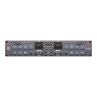
Please note that there are two & buttons in the Matrix channel. The other & button is located further up the channel
strip, above the digital scribble strip, and is concerned with the desk’s analogue routing, not DAW control.
Note that in DAW mode, the channel &"" mode is defined by the DAW, and that the analogue and DAW solo functions
have separate centre section solo indicators.
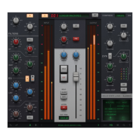
The Digital Scribble Strip
The digital scribble strip that runs across the centre of the desk consists of two display rows. By default, the top row contains
labels associated with the channel faders, and is therefore Focus mode dependent: In Analogue Focus mode it displays the channel
names defined in the 70==4;A tab of the Matrix Remote (switching to a momentary display of the fader value in dB when a fader
is moved), whereas in DAW Focus mode the top row normally displays the DAW track names.
If the desk is in Analogue Focus and the &#, is box is enabled in the 70==4;A tab of the Remote, channel names
17-32 will hi-jack the bottom row of the scribble strip and replace the DAW track names. #&%&'%# will then
allow the two rows of channel names to be reversed, so that 17-32 are shown on the top row.
Please note that the FLIP SCRIBBLE STRIP on the Channels tab is independent to the FLIP SCRIBBLE STRIPS option on the
DAW tab, which is specific to DAW scribble strip information. Read below to find out more about this.
The bottom row of the scribble strip is associated with the V-Pot located beneath the scribble strip. When Matrix is assigned to
a layer controlling a DAW, the bottom row of the scribble strip displays either the name or the value of the parameter controlled
by the V-Pot. When controlling Pro Tools, the scribble strip only displays the name of the V-Pot. For DAWs controlled via the
MCU protocol, please refer to their control surface documentation for full details of their scribble strip displays and messages.
In order to cater for variations in the ways MCU DAWs return channel data, there is a
;8?&2@811;4&B@8?A box in the *
tab of the Remote, located to the right of the 38B#@>58;4A button. This switches the two rows of the scribble strip, allowing
Nuendo labelling to follow the Logic format. ;8?&2@811;4&B@8?A is enabled for the Nuendo default Profile and disabled for the
Logic default Profile. For other MCU DAWs, the labelling format described in their control surface documentation will enable
you to ascertain whether or not to activate this function.
See Page 106 for a description of the scribble strip in CC layers.