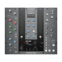
The Channel Strip
Channel Inputs
Each channel on Matrix has two line inputs: The first input would normally be sourced from the
output of a mic preamp, DI box or instrument and is labelled on the back of the desk as ‘LINE
IN’. The second input would normally be fed from the output of the DAW and labelled as ‘DAW
Return’.
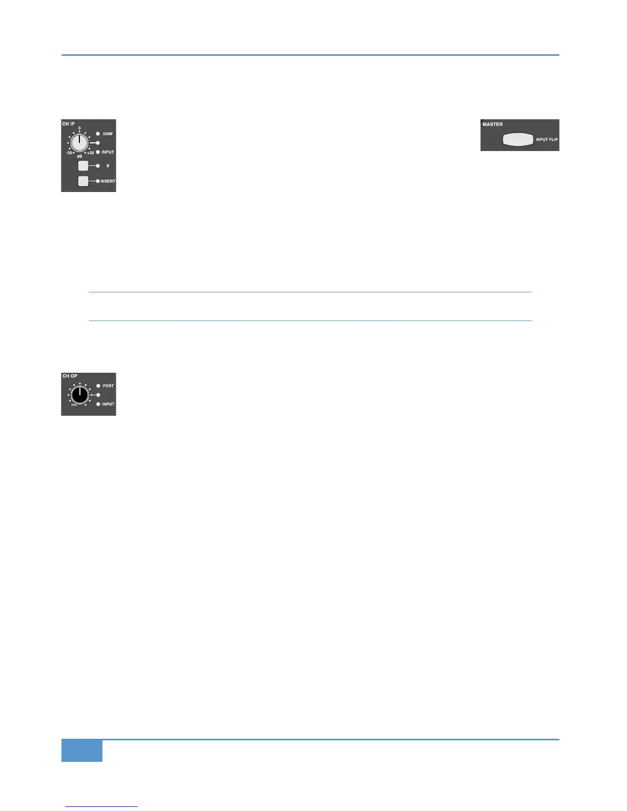
The Channel Input (#) is sourced from the line in by default, and it is this
i
nput that is referred to wherever the
!#('
l
abel appears on the desk. To swap inputs to the DAW return,
press the
!#('# button at the top of the Master Channel. The LEDs to the right of the gain pot indicate
which input is selected, as does the colour of the !#('# button (Green for !#(', red for *).
Once you have selected your input, it then has a ±20dB gain trim, indented in the centre at unity gain with a Total Recall LED,
and phase reverse (ø) button.
The post-gain channel signal is always available to the Insert Matrix. Pressing the
!&%' button brings the return from the Insert
Matrix back into the channel, effectively dropping into the signal chain whatever processing is assigned to it from the Insert Matrix
(see Page 67).
Note that if you press the !&%' button when nothing has been routed to that channel from the Insert Matrix, the
channel strip will be silent beyond the insert point.
Channel Outputs
Direct Channel Outputs
The individual Channel Outputs ("#), are designed to be used to feed the inputs of a DAW, and appear on
the desk’s rear panel as CHANNEL OUT. The "# has a gain trim with an indent in the centre at unity gain,
and a Total Recall LED. It can be fed from three different places: line-in pre-gain (!#('), pre-fader (post-insert)
or #"&'-fader, as selected by the &% button in the "# section of the Master Channel. Pre-fader is the
default setting.
The line-out’s source is indicated by the LEDs to the right of the gain pot and by the colour of the &% button:
Signal Source LED indication SRC button colour
Pre-fader, post-insert (default) No LED Unlit
From the line-in, pre-gain !#(' is lit Red
Post-fader #"&' is lit Yellow