23MS 362, MS 362 C
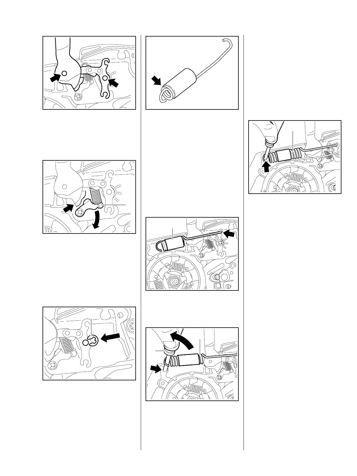
: Lift the bearing boss of the hand
guard and the brake lever a little
and position them over the pivot
pins (arrows).
: Turn the cam lever (1) to one side
until the cam of the hand guard
(arrow) slips passed it.
– Push the hand guard bearing
boss and the brake lever on to
the pivot pins.
: Fit the E-clip (1).
0001RA028 TG
0001RA029 TG
1
0001RA030 TG
1
The turns of brake spring must be
tightly against one another in the
relaxed condition. If this is not the
case, replace the brake spring.
– Position the protective tube so
that it leaves the first turn (arrow)
free.
– If the groove in the spring's
anchor pin is worn, install a new
pin, b 5.6
: Hook the brake spring (1) to the
brake lever (arrow).
: Use the assembly tool (2)
1117 890 0900 to attach the
brake spring (1) to the anchor pin
(arrow).
0001RA013 TG
0001RA031 TG
1
1
2
0001RA032 TG
– Reassemble all other parts in the
reverse sequence.
– Tightening torques, b 2.5
– Lubricate the brake lever, b 15
5.4 Brake Lever on Machines
with QuickStop Super
– Troubleshooting, b 3.2
– Remove the brake band, b 5.2
– Engage the chain brake.
The brake spring is now relaxed.
: Use the assembly tool 1117 890
0900 to disconnect the brake
spring (1) from the anchor pin
(arrow).
– Remove the brake spring from
the brake lever.
0001RA033 TG
1

 Loading...