40 MS 362, MS 362 C
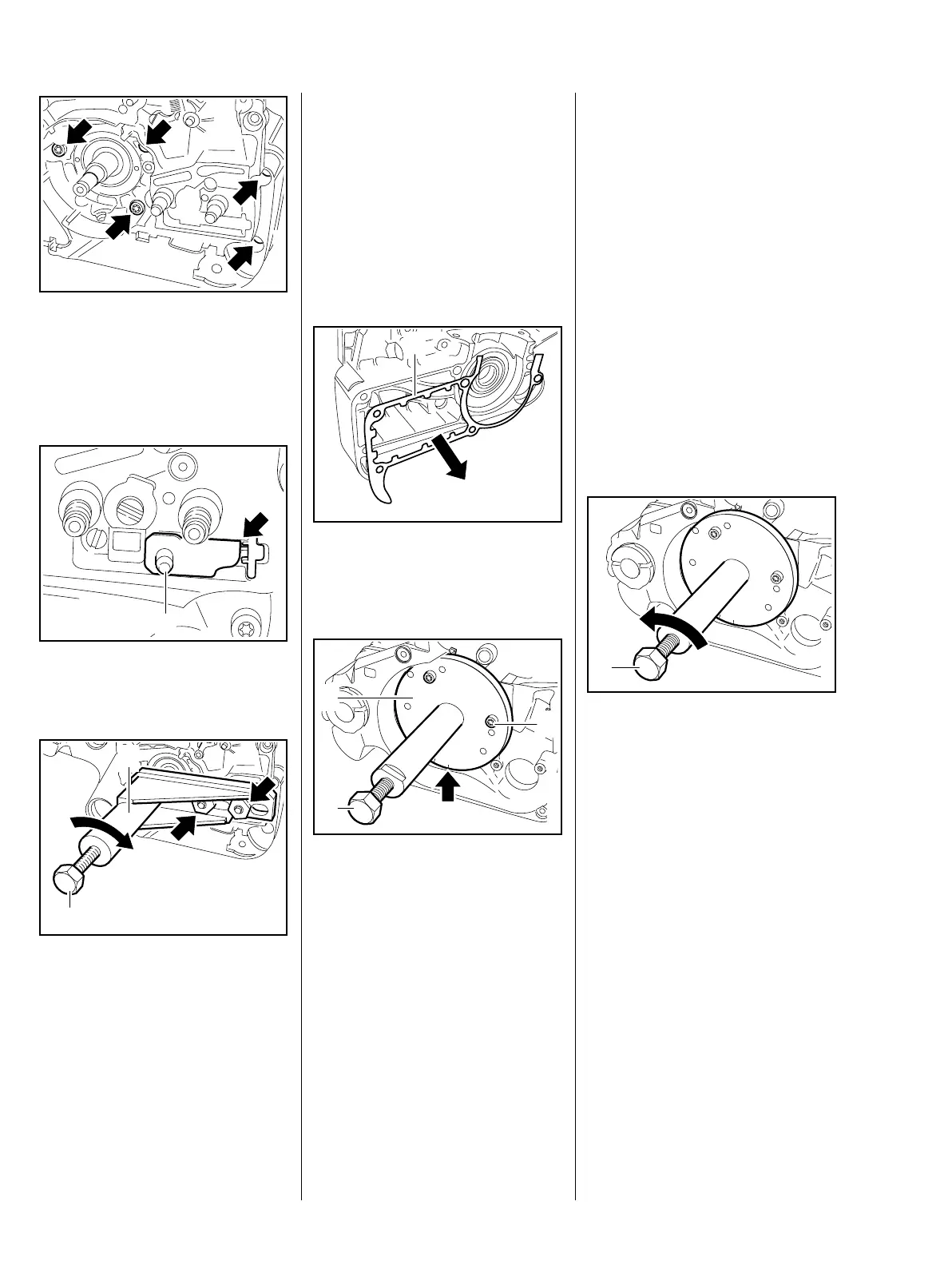
Use the tools in the service tool set
5910 007 2205 for removing and
installing.
: Take out the screws (arrows).
: The tensioner slide (1) must butt
against the thrust pad (arrow).
: Back off the spindle (1) in service
tool until it is clear of the
crankshaft stub.
: Push the service tool (2)
5910 890 2205 over the collar
screws (arrows), fit the nuts and
tighten them down firmly.
0001RA112 TG0001RA113 TG
1
0001RA114 TG
1
2
: Turn the spindle (1) clockwise
until the crankshaft stub is
pushed out of the ball bearing.
This operation releases the clutch
side of the crankcase and separates
the two halves.
– Install new ball bearings and oil
seals, b 6.6.1 and b 6.3
: Remove the gasket (1).
Ignition side of crankcase
Use the tools in the service tool set
5910 007 2201 for removing and
installing.
– Use drilled plate 5910 893 2103.
The drilled plate 5910 893 2103
can be added to and used with
service tool set 5910 007 2200.
0001RA115 TG
1
21
23
21
23
21
22
22
22
22
22
22
0001RA116 TG
1
2
3
All three drilled plates are included
in the new service tool set
5910 007 2201.
– Unscrew the spindle of service
tool (1) until the drilled plate (2)
butts against the crankcase
– left-hand thread.
: Service tool (1) with plate (2)
5910 893 2103 against the
ignition side of the crankcase so
that the number "22" (arrow) is at
the bottom.
: Insert three M5x72 screws (3) in
the holes marked "22" and
tighten them down until they butt
against the crankcase.
: Turn the spindle (1)
counterclockwise until the
crankshaft is pushed out of the
ignition side of the crankcase.
22
21
21
22
22
0001RA117 TG
1

 Loading...