41MS 362, MS 362 C
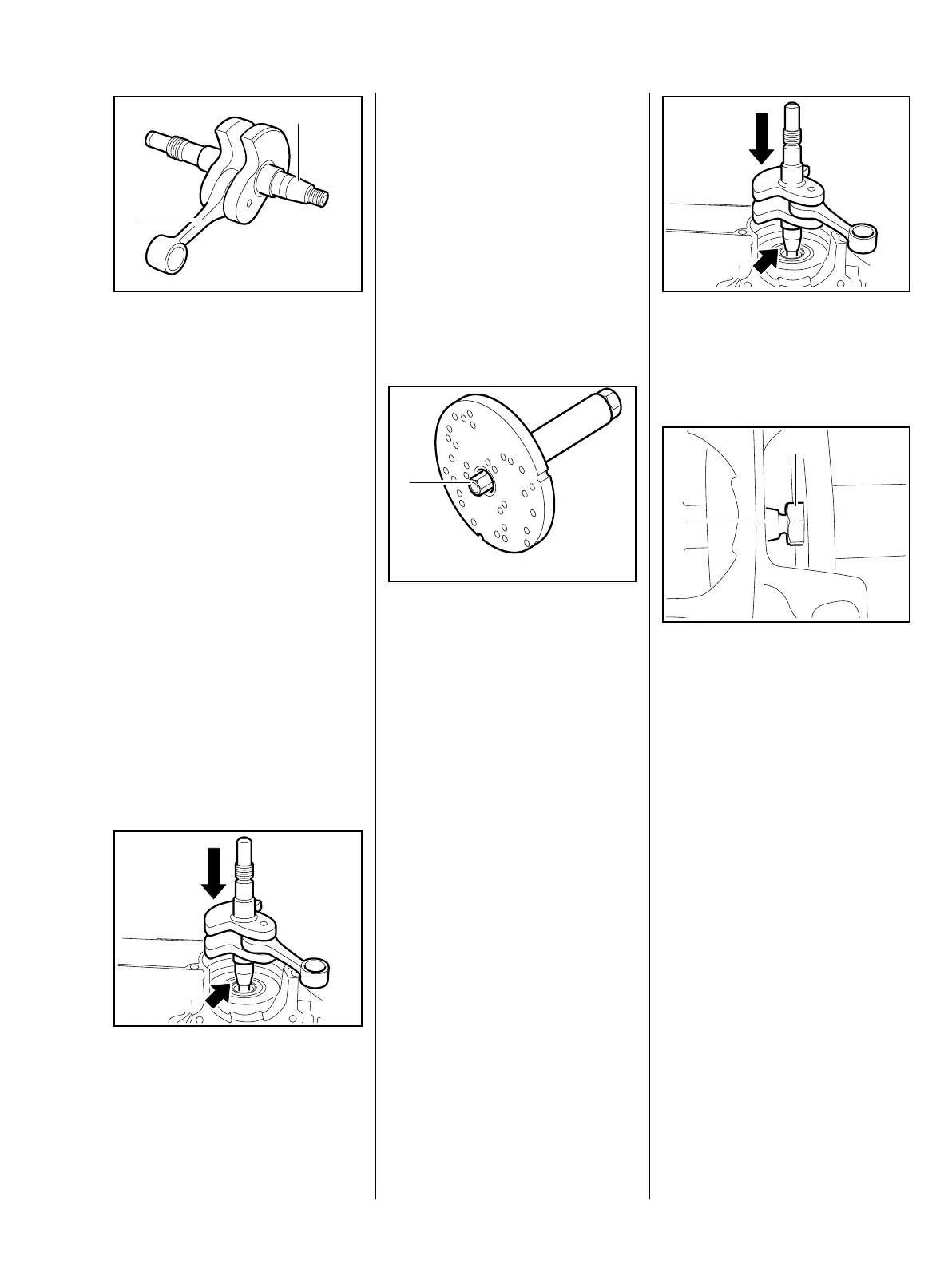
The crankshaft (1), connecting rod
(2) and needle bearing form an
inseparable unit. Always replace as
a complete unit.
– Check the two halves of the
crankcase and ball bearings and
replace if necessary, b 6.6.1
Before installing, clean the
crankshaft with a standard
commercial, solvent-based
degreasant containing no
chlorinated or halogenated
hydrocarbons.
Installing
Ignition side of crankcase
Take care not to damage the
crankshaft stub.
Sealing faces must not be damaged
in any way.
: Position the tapered stub of the
crankshaft (arrow) above the ball
bearing at the ignition side.
0001RA118 TG
1
2
0001RA119 TG
– Wear protective gloves
to reduce risk of burn injury.
– Heat the inner bearing race to
about 150°C (300°F).
: Push the crankshaft home as far
as stop.
This operation must be carried out
very quickly because heat is
absorbed by the crankshaft, and the
inner bearing race shrinks.
If it is not possible to heat the inner
bearing race, use service tool 5910
007 2200 or 5910 007 2201 to install
the crankshaft.
– Use drilled plate 5910 893 2103.
: Screw the threaded sleeve (1)
5910 893 2420 onto the spindle
as far as stop.
Coat tapered stub of crankshaft with
oil.
0001RA120 TG
1
.
: Position the tapered stub of the
crankshaft (arrow) above the ball
bearing at the ignition side and
push it home.
: Position the screw sleeve (2) on
the crankshaft thread (1) and
screw it into place.
0001RA119 TG
0001RA122 TG
1
2

 Loading...