76 MS 362, MS 362 C
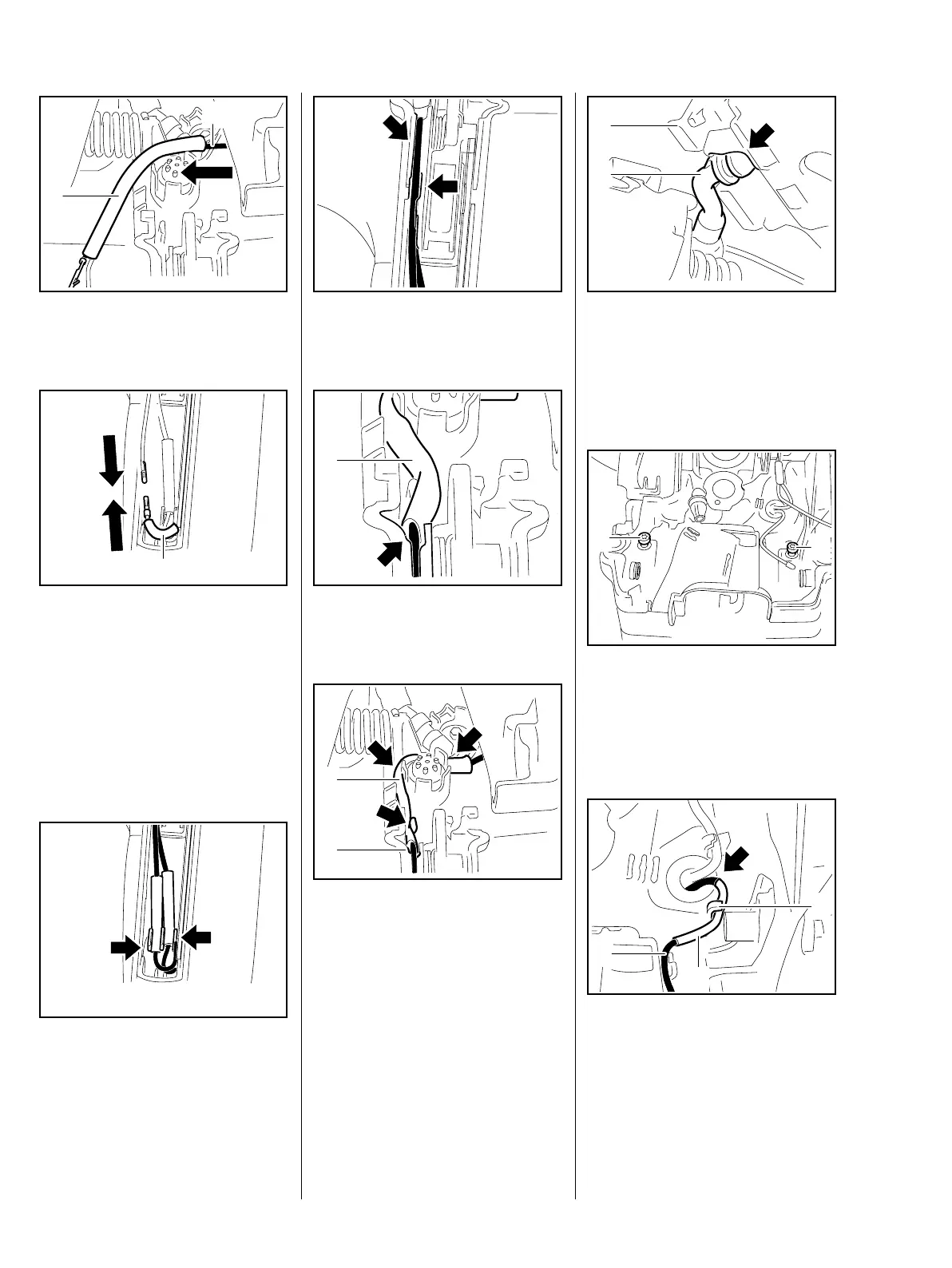
: Push the wires (1) through the
insulating tube (2).
– Before placing the wires in
position, make sure they are the
same length.
: Push the pins and sockets
together until they lock.
: Push the insulating tube (1) over
the connector.
– Insulating tubes must be located
in the guides (arrows).
0001RA256 TG
2
1
0001RA257 TG
1
0001RA357 TG
: Push the wires into the guides
(arrows).
: Position the insulating tube (1) so
that it is against the edge (arrow).
: Starting from the edge (1), push
the insulating tube (2) into the
guides (arrows).
Make sure the wires are laid neatly
and straight (no loops).
0001RA476 TG0001RA401 TG
1
0001RA243 TG
1
2
: Pass the fuel hose (1) through
the opening (arrow).
– Place the air guide shroud (2) in
position.
: Fit and tighten down the screws
(1) firmly.
Make sure that the wires are not
pinched.
: Position the wire (1) so that the
insulating tube (2) is against the
edge of the grommet (arrow).
: Fit the wire in the guide (3).
0001RA261 TG
1
2
0001RA340 TG
1
1
0001RA264 TG
2
3
1

 Loading...