Bed Circuit Boards
52
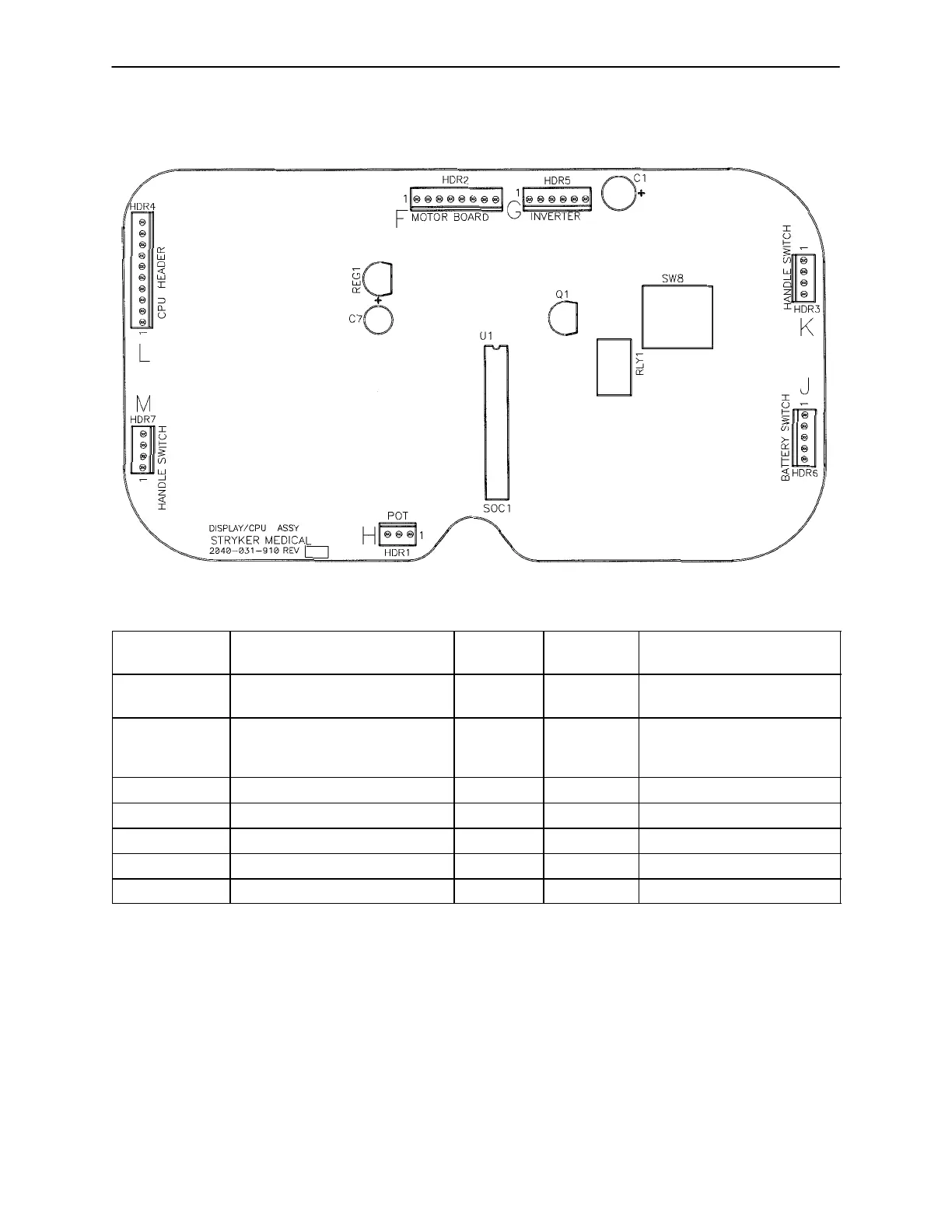
ZOOMR OPTION DISPLAY/CPU − P/N 2040−31−910
CONNECTOR
LOCATION
VOLTAGE POSITIVE
LEAD
NEGATIVE
LEAD
DESCRIPTION
HDR 1 (H) 0−5VDC Pin 1 Pin 2 Control Pot Wiper Voltage
(with Switch On)
HDR 6 (J) Battery voltage around 26VDC Pin 1 Pin 5 Battery Voltage Return
from On/Off Switch
(with Switch On)
HDR 4 (L) 5VDC Pin 9 Pin 1 Voltage from CPU
HDR 1 5VDC Pin 1 Pin 3 DC Voltage to Pot
HDR 7 Continuity Pin 1 Pin 4 Right Hand Switch
HDR 3 Continuity Pin 1 Pin 4 Left Hand Switch
HDR 2 26VDC Pin 3 Pin 1 Battery Voltage

 Loading...