Appendix C Functional Description C-7
operations used for two-dimensional image processing, two and three-dimensional
graphics, image compression algorithms, and parallel operations on pixel data with
8- and 16-bit components.
C.2.3 Memory Controller
The memory system consists of the memory control unit (MCU) in the CPU, and two
physical banks (B0 and B1) of DDR-1 synchronous DRAM memory. Only registered
DIMMS are supported.
Clock buffering with a PLL is provided on the DIMMs. Each physical bank consists
of two 128-bit DDR-1 SDRAM DIMMs. These two DIMMs share an 8-byte data bus
and an ECC data bus. Both physical banks share an address/control bus. Since each
DIMM could be dual sided (upper and lower banks), there are maximum of four
data loads per physical bank. The cache line is split across the two physical banks.
Both banks are controlled by the memory controller.
Note – DIMMs must always be installed in pairs.
A memory controller sends requests in the pipeline, using 16 memory banks in the
Sun Ultra 45 when fully loaded, and 8 memory banks in the Sun Ultra 25 when fully
loaded.
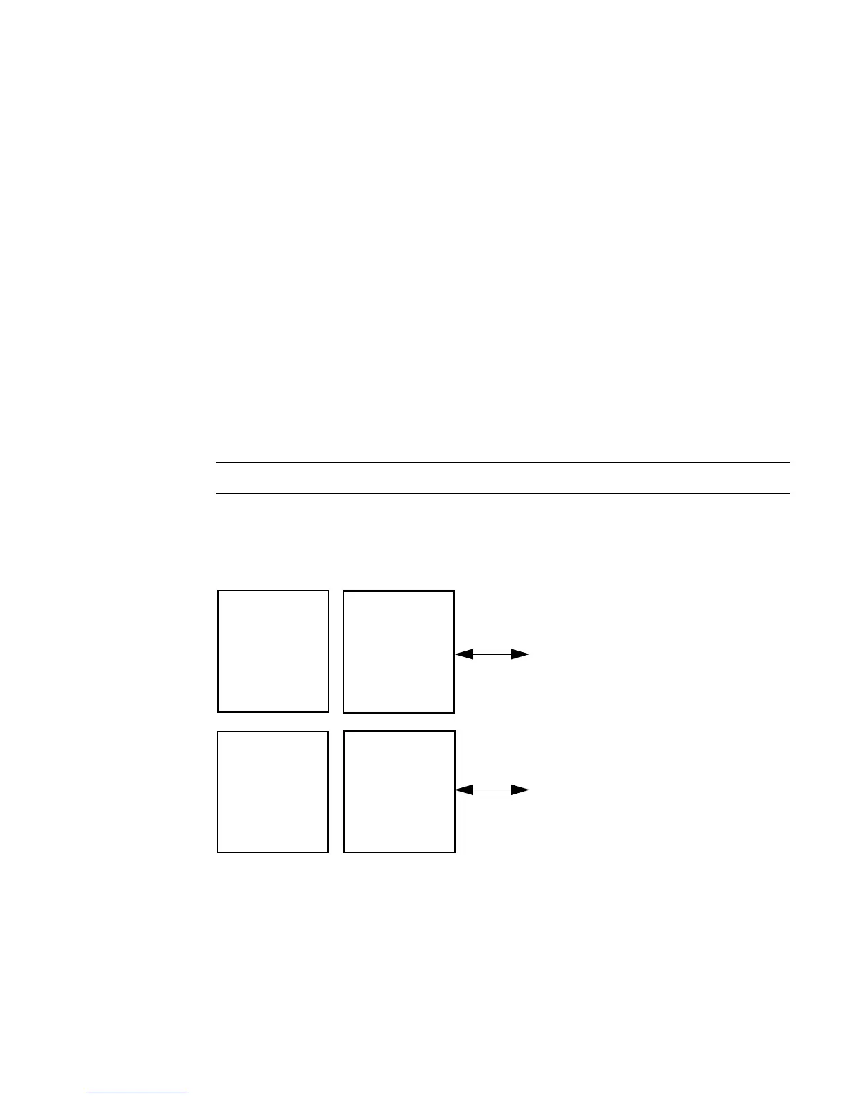
FIGURE C-4 UltraSPARC IIIi Chip Architecture
UltraSPARC IIIi
1 MB L2 cache
DDR-1 memory
JBUS interface
DDR 266
core
controller
SDRAM interface
128-bit data, 9-bit ECC
JBUS interface
128-bit data, 36-bit address
200 MHz