13-6 ELECTRICAL SYSTEM
Step 8
1) Measure the exciter coil and charge coil resistance. (13-7)
Is the exciter coil and charge coil OK?
IGNITION SYSTEM
IGNITION SYSTEM PEAK VOLTAGE
INSPECTION
• Remove the seat and fuel tank. (5-3)
• Remove the spark plug.
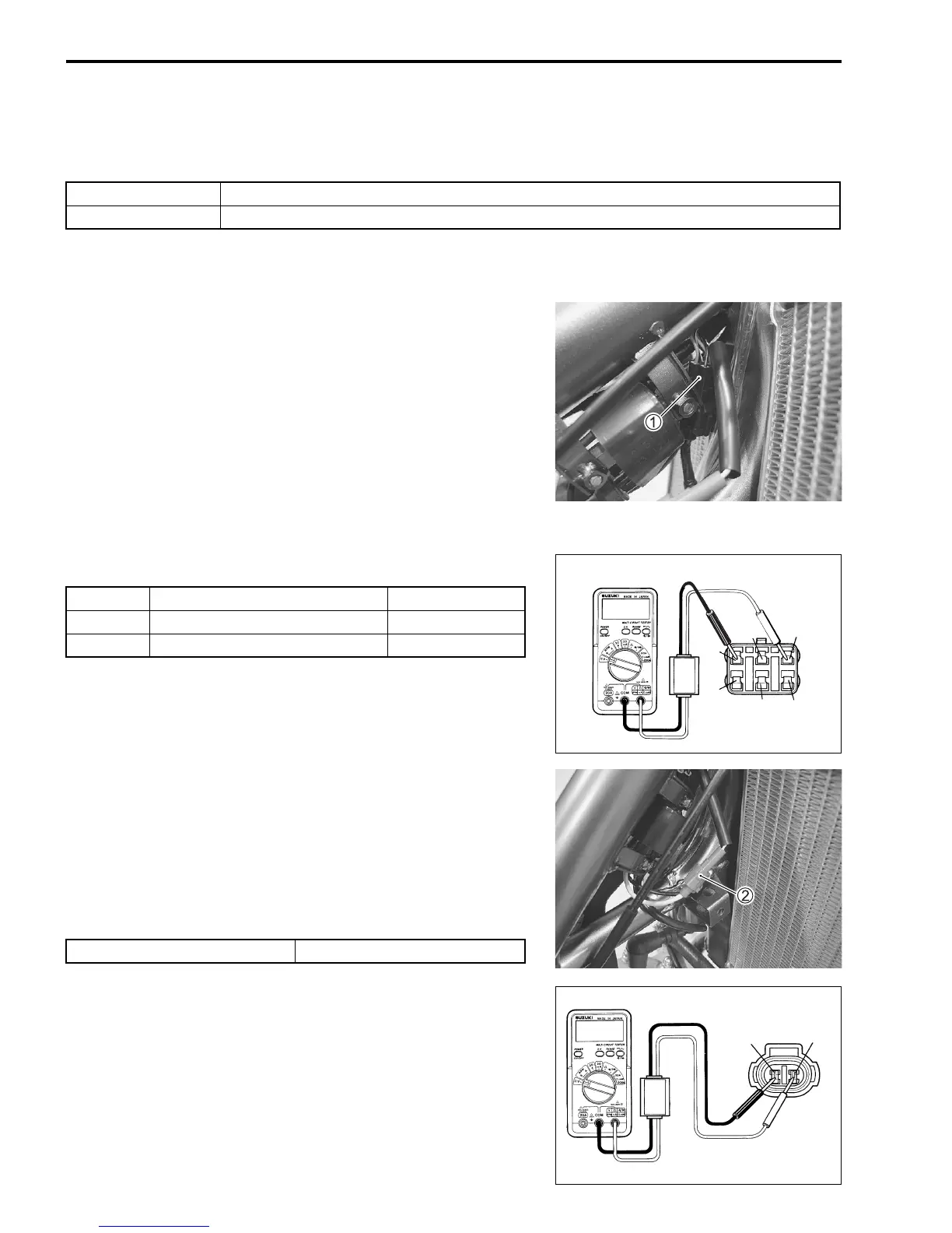
• Disconnect the magneto lead wire coupler 1.
Measure the ignition system peak voltage in the following proce-
dure:
• Connect the multi circuit tester with peak volt adaptor as fol-
lows. (See table below.)
• Measure the highest peak voltage by depressing the kick
starter lever several times forcefully.
09900-25008: Multi circuit tester set
Tester knob indication: Voltage ()
• Connect the magneto lead wire coupler and disconnect the
ignition coil lead wire coupler 2.
• Connect the multi circuit tester with peak volt adaptor
between Black/White lead wire and White/Blue lead wire.
• Measure the highest peak voltage by depressing the kick
starter lever several times forcefully.
NOTE:
Be sure the Red probe pin to connected to the Black/White lead
wire and Black probe pin to the White/Blue lead wire.
YES Faulty CDI
NO Faulty magneto
Exciter + Black/Red – - Red/White 25 V and more
Pick-up + Red – - Green 2 V and more
Charge + Yellow – - Black/White 8 V and more
R/W
G
R
B/R
Y
B/W
+
Black/White –
-
White/Blue
200 V and more
B/W
W/BI