MACHINE TUNING 4-3
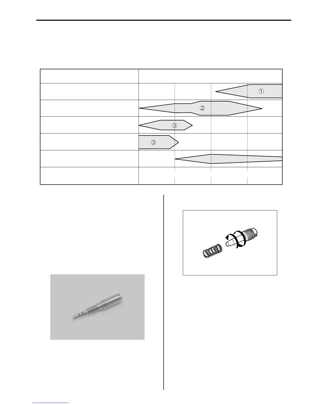
As shown below, each tuning part is located between the air/fuel passage and has its own air/fuel mixture
adjustable range in terms of the throttle valve opening. The chart indicates that the carburetor can supply
correct air/fuel mixture to the engine in any range because of the overlapping adjustable range of the each
part.
1 MAIN SYSTEM 2 INTERMEDIATE SYSTEM 3 PILOT SYSTEM
When performing carburetor tuning, first find out in
what throttle opening range an improper air/fuel
mixture is supplied, by checking the color of
exhaust smoke, spark plug, throttle response,
power, etc. Second, replace or adjust the part(s)
related to the throttle opening range by referring to
the following instructions. The sizes referred to in
the illustrations are those of standard setting.
PILOT JET
The pilot jet meters the fuel supplied to the pilot sys-
tem. Each jet size is indicated by a number. Larger
number means a larger bore diameter and fitting a
larger numbered pilot jet enriches the air/fuel mix-
ture.
AIR SCREW
The air screw is located in the inlet air passage and
meters the air for the slow system. As it has a
right-hand thread, tightening it makes the passage
narrower, allowing less amount of intake air to flow
and resulting in richer air/fuel mixture. Air flow
adjustment is effective within a range of 1/2 – 2
turns out.
POWER JET
The power jet supplies the necessary amount of
fuel to the carburetor bore for correcting fuel/air
mixture ratio. When engine speed is 9 000 to
11 000 r/min, the passage is opened by solenoid
valve. The solenoid valve opens the passage when
the current not flows from CDI unit.
TUNING PARTS THROTTLE VALVE OPENING
MAIN JET
JET NEEDLE CLIP POSITION
JET NEEDLE O.D.
PILOT JET AND AIR SCREW
POWER JET
THROTTLE OPENING
1/41/4 1/2 3/4
Rich
Lean
 Loading...


