Performance Check Procedure
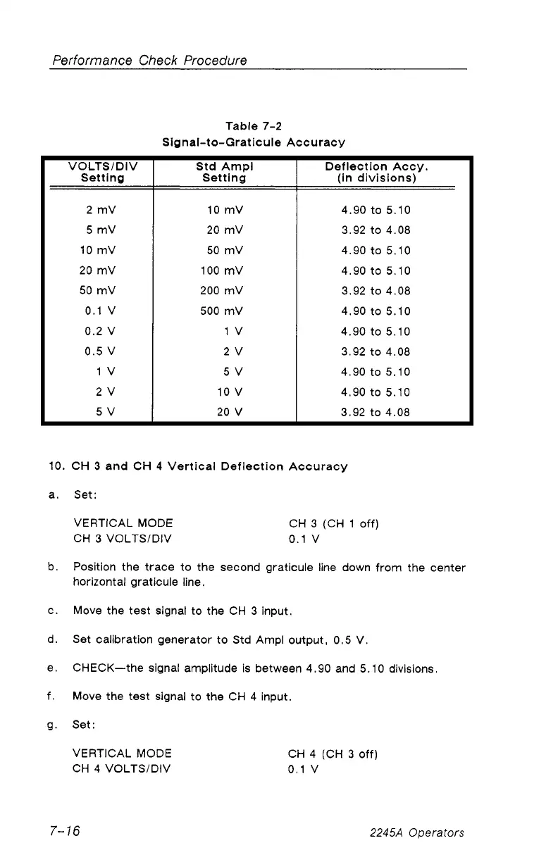
Table 7-2
Signal-to-G raticule Accuracy
VOLTS/DIV
Setting
Std Ampl
Setting
Deflection Accy.
(in divisions)
2 mV 10 mV
4.90 to 5.10
5 mV 20 mV 3.92 to 4.08
10 mV 50 mV
4.90 to 5.10
20 mV
100 mV 4.90 to 5.10
50 mV 200 mV
3.92 to 4.08
0.1 V 500 mV
4.90 to 5.10
0.2 V 1 V
4.90 to 5.10
0.5 V 2 V
3.92 to 4.08
1 V
5 V 4.90 to 5.10
2 V 10 V
4.90 to 5.10
5 V 20 V
3.92 to 4.08
10. CH 3 and CH 4 Vertical Deflection Accuracy
a. Set:
VERTICAL MODE CH 3 (CH 1 off)
CH 3 VOLTS/DIV 0.1V
b. Position the trace to the second graticule line down from the center
horizontal graticule line.
c. Move the test signal to the CH 3 input.
d. Set calibration generator to Std Ampl output, 0.5 V.
e. CHECK—the signal amplitude is between 4.90 and 5.10 divisions.
f. Move the test signal to the CH 4 input.
g. Set:
VERTICAL MODE CH 4 (CH 3 off)
CH 4 VOLTS/DIV 0.1V
7-16
2245A Operators