Basic Applications
Introduction
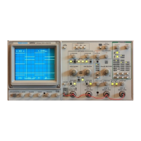
The TEKTRONIX 2245A Oscilloscope has a cursor measurement system
for making accurate, direct-readout voltage, time, and frequency
measurements. The measurements given in this section are examples of
typical applications using this measurement system. After becoming
familiar with the controls, indicators, and capabilities of the instrument, you
can develop convenient methods for making special measurements for your
own applications. A brief description of how the graticule markings are used
in making measurements is given in Section 3 of this manual.
When a procedure calls for “Initial Setup” or “Auto Setup Function,” refer
to the “OPERATOR CHECKS AND ADJUSTMENTS” Section 4. Certain
signals such as video or aperiodic (non-repeating) signals and signals con
taining many unrelated frequency components may require more
adjustment of the triggering controls to obtain the best display.
Voltage Measurement Cursors
The CURSOR VOLTS function can accurately measure signals displayed on
CH I or CH 2. Voltage measurements using the cursors may also be done
on CH 3, CH 4, and ADD waveforms by setting the VOLTS/DIV switch set
ting of the selected measurement channel to the same scale factor as the
signal to be measured. However, measurements on CH 3 or CH 4 input
signals will be less accurate than on the CH 1 or CH 2 input signals. Volts
cursors are available for making measurements in the both the A and X-Y
horizontal modes.
Voltage Difference
Use the following procedure steps as a guideline in making voltage-
difference measurements using the positionable voltage cursors.
1. Apply the signal to the CH 1 input connector.
2. Set:
Vertical MODE CH 1
Horizontal MODE A
3. Press AUTO SETUP button.
2245A Operators
5-1

 Loading...