Performance Check Procedure
8. Delay Time Accuracy
a. Set:
ALT
10 jjis
Fully CCW (maximum
downward position)
To display both the ALT
and the B Delayed Traces
b. Position the intensified dot to full left position (counter-clockwise rota
tion of the |<- o r DELAY control).
c. Align the leading edge of the time marker displayed on the B trace to
the left-most (first) graticule line, using only the Horizontal POSITION
control.
d. CHECK—that the readout is ?0.000 ms.
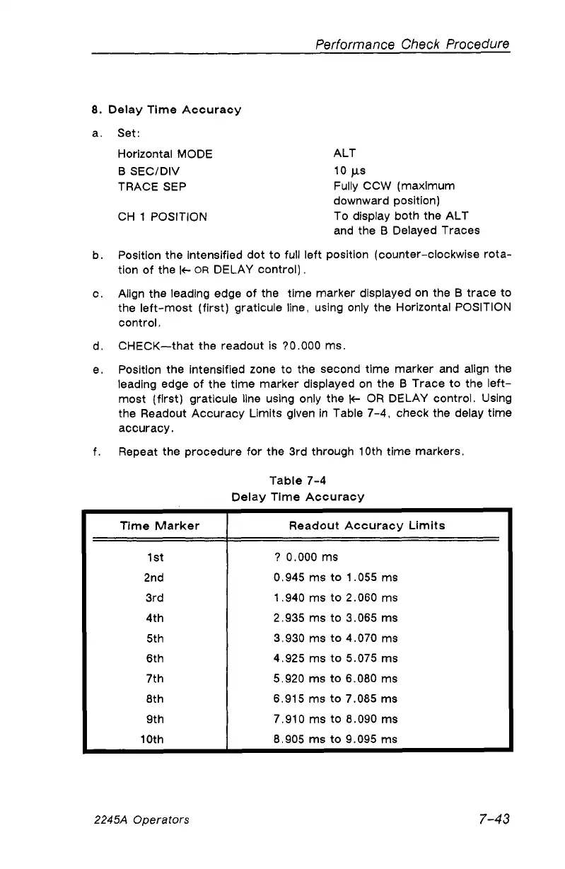
e. Position the intensified zone to the second time marker and align the
leading edge of the time marker displayed on the B Trace to the left
most (first) graticule line using only the K- OR DELAY control. Using
the Readout Accuracy Limits given in Table 7-4, check the delay time
accuracy.
f. Repeat the procedure for the 3rd through 10th time markers.
Table 7-4
Delay Time Accuracy
Time Marker
Readout Accuracy Limits
1st
? 0.000 ms
2nd
0.945 ms to 1.055 ms
3rd
1.940 ms to 2.060 ms
4th
2.935 ms to 3.065 ms
5th
3.930 ms to 4.070 ms
6th 4.925 ms to 5.075 ms
7th 5.920 ms to 6.080 ms
8th 6.915 ms to 7.085 ms
9th 7.910 ms to 8.090 ms
10th
8.905 ms to 9.095 ms
Horizontal MODE
B SEC/DIV
TRACE SEP
CH 1 POSITION
2245A Operators
7-43