Appendix A
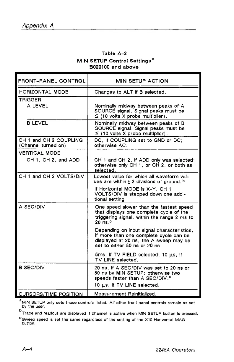
Table A-2
MIN SETUP Control Settings3
B020100 and above
FRONT-PANEL CONTROL MIN SETUP ACTION
HORIZONTAL MODE
Changes to ALT if B selected.
TRIGGER
A LEVEL
Nominally midway between peaks of A
SOURCE signal. Signal peaks must be
< (10 volts X probe multiplier).
B LEVEL
Nominally midway between peaks of B
SOURCE signal. Signal peaks must be
< (10 volts X probe multiplier).
CH 1 and CH 2 COUPLING
(Channel turned on)
DC, if COUPLING set to GND or DC;
otherwise AC.
VERTICAL MODE
CH 1, CH 2, and ADD
CH 1 and CH 2, if ADD only was selected;
otherwise only CH 1, or CH 2, or both as
selected.
CH 1 and CH 2 VOLTS/DIV
Lowest value for which all waveform val
ues are within + 2 divisions of ground. b
If Horizontal MODE Is X-Y, CH 1
VOLTS/DIV is stepped down one addi
tional setting
A SEC/DIV
One speed slower than the fastest speed
that displays one complete cycle of the
triggering signal, within the range 2 ms to
20 ns.°
Depending on Input signal characteristics,
if more than one complete cycle can be
displayed at 20 ns, the A sweep may be
set to either 50 ns or 20 ns.
5ms, if TV FIELD selected; 10 (is, If
TV LINE selected.
B SEC/DIV
20 ns, if A SEC/DIV was set to 20 ns or
50 ns by MIN SETUP; otherwise two
speeds faster than A SEC/DIV.0
10 fis, if TV LINE selected.
CURSORS/TIME POSITION
Measurement Reinitialized.
MIN SETUP only sets those controls listed. All other front panel controls remain as set
by the user.
b
Trace and readout are displayed if channel is active when MIN SETUP button is pressed.
c Sweep speed is set the same regardless of the setting of the X10 Horizontal MAG
button.
A-4
2245A Operators