Controls, Connectors, and Indicators
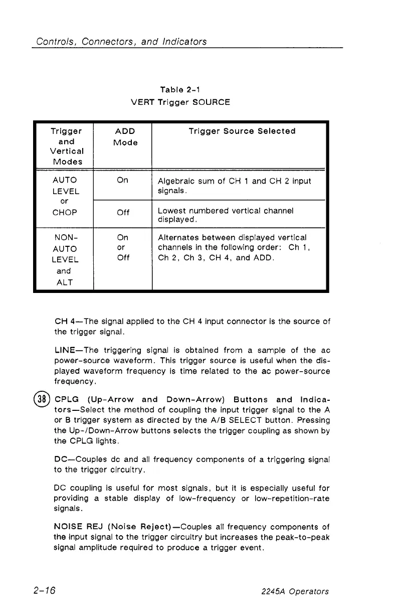
Table 2-1
VERT Trigger SOURCE
Trigger
and
Vertical
Modes
ADD
Mode
Trigger Source Selected
AUTO
LEVEL
or
CHOP
On
Algebraic sum of CH 1 and CH 2 input
signals.
Off
Lowest numbered vertical channel
displayed.
NON
AUTO
LEVEL
and
ALT
On
or
Off
Alternates between displayed vertical
channels in the following order: Ch 1,
Ch 2, Ch 3, CH 4, and ADD.
CH 4—The signal applied to the CH 4 input connector is the source of
the trigger signal.
LINE—The triggering signal is obtained from a sample of the ac
power-source waveform. This trigger source is useful when the dis
played waveform frequency is time related to the ac power-source
frequency.
(3 8 )
CPLG (Up-Arrow and Down-Arrow) Buttons and Indica
tors—Select the method of coupling the input trigger signal to the A
or B trigger system as directed by the A/B SELECT button. Pressing
the Up-/Down-Arrow buttons selects the trigger coupling as shown by
the CPLG lights.
DC—Couples dc and all frequency components of a triggering signal
to the trigger circuitry.
DC coupling is useful for most signals, but it is especially useful for
providing a stable display of low-frequency or low-repetition-rate
signals.
NOISE REJ (Noise Reject)—Couples all frequency components of
the input signal to the trigger circuitry but increases the peak-to-peak
signal amplitude required to produce a trigger event.
2-16
2245A Operators