Operators Familiarization
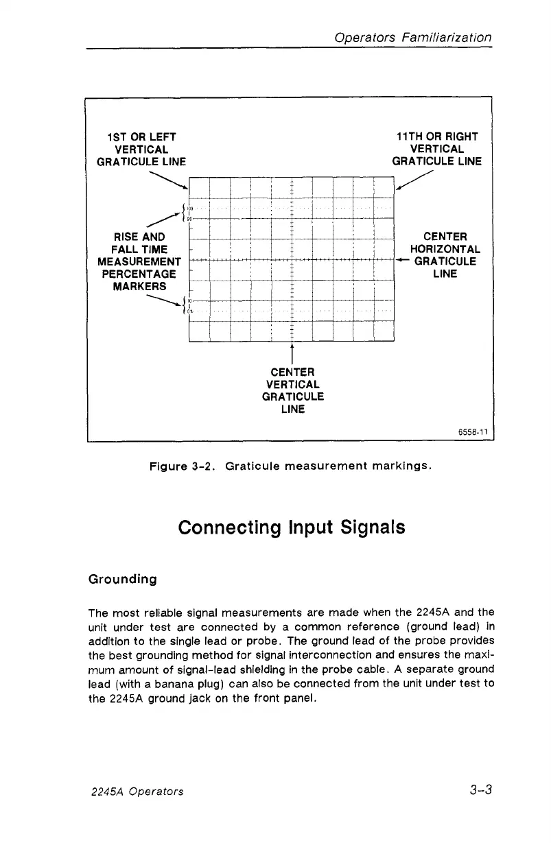
1ST OR LEFT
VERTICAL
GRATICULE LINE
11TH OR RIGHT
VERTICAL
GRATICULE LINE
RISE AND
FALL TIME
MEASUREMENT
PERCENTAGE
MARKERS
CENTER
HORIZONTAL
0 ■ ■
-
-
,
-
GRATICULE
LINE
-
0
CEN
VER1
GRAT
LI
TER
rICAL
ICULE
NE
6558-11
Figure 3-2. Graticule measurement markings.
Connecting Input Signals
Grounding
The most reliable signal measurements are made when the 2245A and the
unit under test are connected by a common reference (ground lead) in
addition to the single lead or probe. The ground lead of the probe provides
the best grounding method for signal interconnection and ensures the maxi
mum amount of signal-lead shielding in the probe cable. A separate ground
lead (with a banana plug) can also be connected from the unit under test to
the 2245A ground jack on the front panel.
2245A Operators
3-3