Appendix A
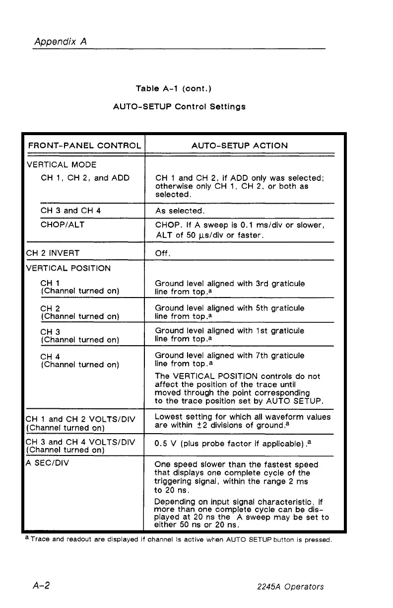
Table A-1 (cont.)
AUTO-SETUP Control Settings
FRONT-PANEL CONTROL
AUTO-SETUP ACTION
VERTICAL MODE
CH 1, CH 2, and ADD
CH 1 and CH 2, if ADD only was selected;
otherwise only CH 1, CH 2, or both as
selected.
CH 3 and CH 4
As selected.
CHOP/ALT
CHOP. If A sweep is 0.1 ms/div or slower,
ALT of 50 |is/div or faster.
CH 2 INVERT
Off.
VERTICAL POSITION
CH 1
(Channel turned on)
Ground level aligned with 3rd graticule
line from top.3
CH 2
(Channel turned on)
Ground level aligned with 5th graticule
line from top.3
CH 3
(Channel turned on)
Ground level aligned with 1st graticule
line from top.3
CH 4
(Channel turned on)
Ground level aligned with 7th graticule
line from top.3
The VERTICAL POSITION controls do not
affect the position of the trace until
moved through the point corresponding
to the trace position set by AUTO SETUP.
CH 1 and CH 2 VOLTS/DIV
(Channel turned on)
Lowest setting for which all waveform values
are within +2 divisions of ground.3
CH 3 and CH 4 VOLTS/DIV
(Channel turned on)
0.5 V (plus probe factor if applicable) 3
A SEC/DIV
One speed slower than the fastest speed
that displays one complete cycle of the
triggering signal, within the range 2 ms
to 20 ns.
Depending on input signal characteristic, if
more than one complete cycle can be dis
played at 20 ns the A sweep may be set to
either 50 ns or 20 ns.
a Trace and readout are displayed if channel is active when AUTO SETUP button is pressed,
A-2
2245A Operators