Controls, Connectors, and Indicators
DC—Couples dc and all frequency components of the input signal to
the vertical attenuator when the DC button is lit.
Turning on DC coupling turns off AC coupling. With DC Coupling se
lected, a DC symbol ( ) is displayed to the right of the associated
VOLTS/DIV readout. Input resistance is 1 M il to ground.
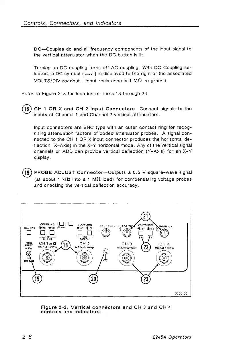
Refer to Figure 2-3 for location of items 18 through 23.
18) CH 1 OR X and CH 2 Input Connectors—Connect signals to the
inputs of Channel 1 and Channel 2 vertical attenuators.
Input connectors are BNC type with an outer contact ring for recog
nizing attenuation factors of coded attenuator probes. A signal con
nected to the CH 1 OR X input connector produces the horizontal de
flection (X-Axis) in the X-Y horizontal mode. Any of the vertical signal
channels or ADD can provide vertical deflection (Y-Axis) for an X-Y
display.
(19) PROBE ADJUST Connector—Outputs a 0.5 V square-wave signal
(at about 1 kHz into a 1 M fl load) for compensating voltage probes
and checking the vertical deflection accuracy.
Figure 2-3. Vertical connectors and CH 3 and CH 4
controls and indicators.
2-6 2245A Operators