EasyManuals Logo

Tektronix GeoProbe G10 Installation Guide

Tektronix GeoProbe G10
168 pages
To Next Page IconTo Next Page
To Previous Page IconTo Previous Page
Page #27 background imageLoading...
Page #27 background image
G10 Installation Guide 7.13.2 27
2
Install Hardware and Power Cabling
Rev. 005-140228
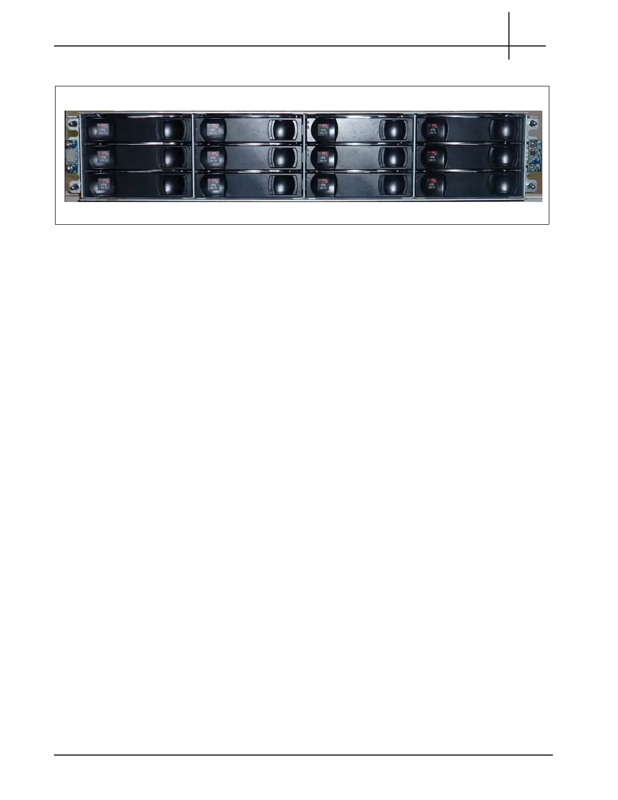
3. SA210J: Remove the enclosure front bezel.
Figure 2.9 - SA210J Storage Enclosure (Bezel Removed)
4. Align the side brackets on the sides of the storage enclosure and secure them
using six to
eight Phillips flat head screws. Alignment varies per rack depth:
30-inch rack (does not use the side bracket)
36-inch rack (see Figure 2.10)
1000 MM rack (see Figure 2.11)
42-inch rack (see Figure 2.12)
Tektronix Communications | For Licensed Users | Unauthorized Duplication and Distribution Prohibited

Table of Contents

Other manuals for Tektronix GeoProbe G10

Questions and Answers:

Question and Answer IconNeed help?

Do you have a question about the Tektronix GeoProbe G10 and is the answer not in the manual?

Tektronix GeoProbe G10 Specifications

General IconGeneral
BrandTektronix
ModelGeoProbe G10
CategoryAccessories
LanguageEnglish