G10 Installation Guide 7.13.2 63
4
Power On G10 and Configure Network Connectivity
Rev. 005-140228
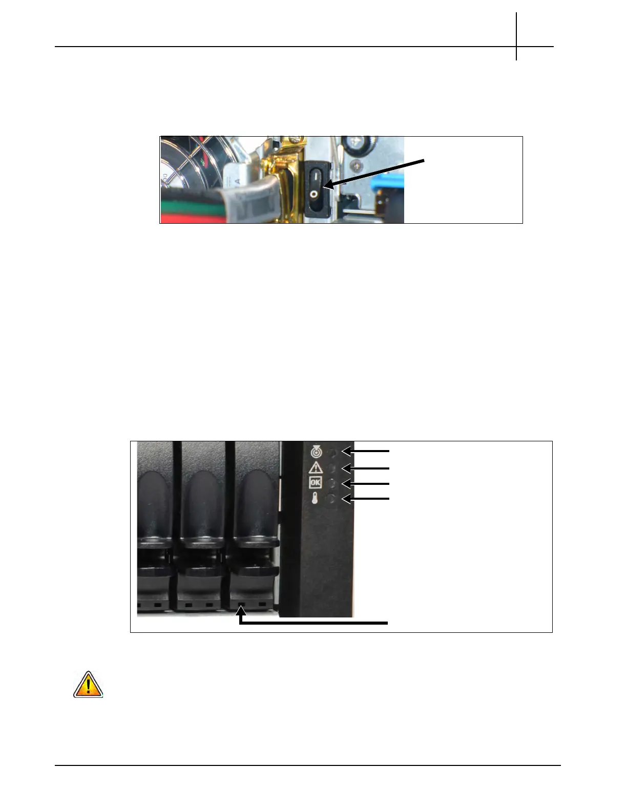
3. Power on the storage arrays. Power on the expansion enclosures first, then the
controller enclosures.
a. Press the power switches to the ON p
o
sition on both power modules at the
back of each enclosure. Figure 4.1 shows the DC power switches.
Figure 4.1 - Storage Enclosure DC Power Switch (Right)
b. Verify the following storage enclosure LEDs (Figu
re 4.2):
Unit Locator ID LED is OFF indicating normal operation
Fault/Service Required LED is OFF indicating no fault conditions
FRU OK (Heartbeat) LED is GREEN indicating the enclosure is
powered on with at least one power supply operating normally
Temperature Fault LED is GREEN indicating enclosure temperatures
are normal
All disk module Power LEDs are GREEN indicating the module is
operating normally
Figure 4.2 - Storage Enclosure LEDs (Front Right View)
Ensure all Storage Enclosures are powered on and operating normally before
continuing with this procedure.
Enclosure
Power Switch
ON position
Unit Locator ID LED
Fault/Service Required ID LED
FRU OK (Heartbeat) LED
Temperature Fault
Disk Module Power LED
Tektronix Communications | For Licensed Users | Unauthorized Duplication and Distribution Prohibited

 Loading...