G10 Installation Guide 7.13.2 64
4
Power On G10 and Configure Network Connectivity
Rev. 005-140228
4. Perform one of the following:
DC Units: Verify that the green IN LED is ON and that the REVERSE LED
is OFF.
- If the green IN LED is OFF or the red REVERSE LED is ON, refer to
Tab
le C.1 on page 112 before proceeding.
- If the green IN LED is ON, press the ON/OFF switch to the ON position on
both PEMs on the front of the G10 chassis (Figure 4.3). The
BACKPLANE LEDs will illuminate green indicating the PEM is sending
power through the backplane.
AC Units: Connect the AC power cables into the rack power outlets. Verify
that the STATUS LED is GREEN.
- If the STATUS LED is not green, refer to Tab
le C.2 on page 114
before proceeding.
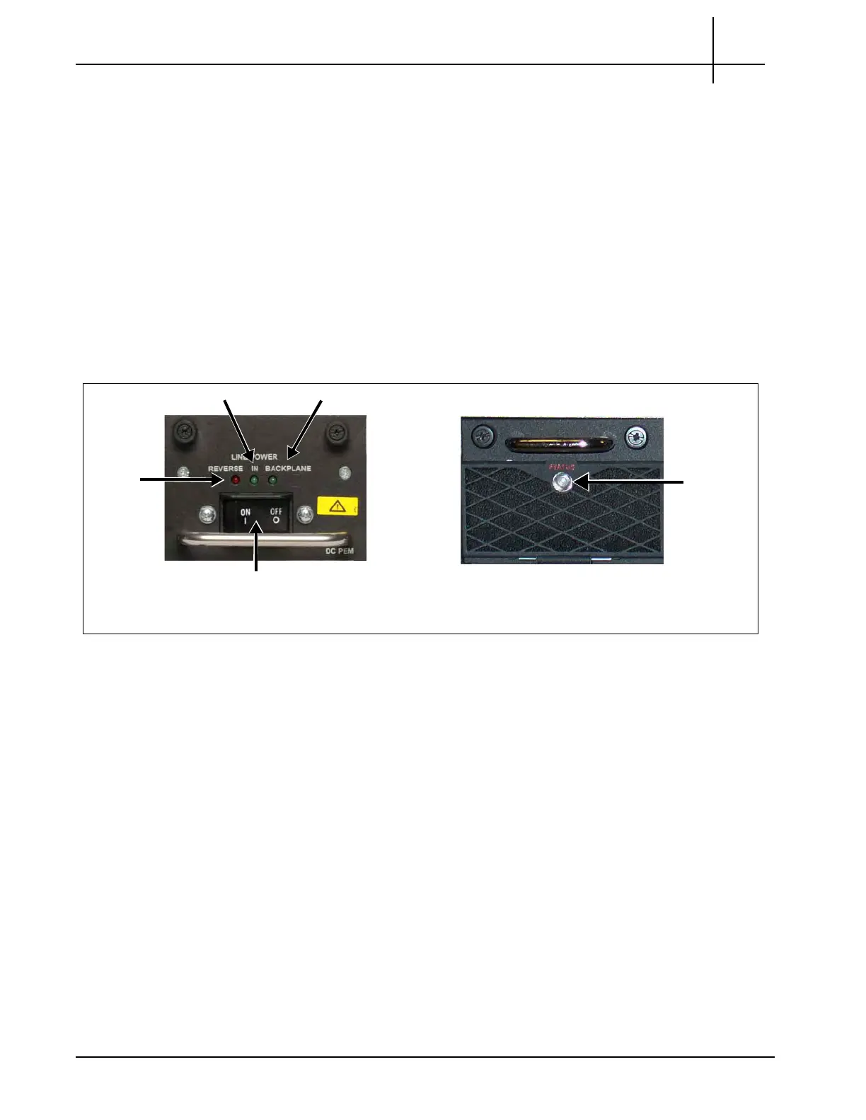
Figure 4.3 - G10 DC and AC PEM Front Panels
5. Verify the following LEDs on the front of the IIC (Figure 4.4):
The + LED on the IIC100/IIC200 is OFF, indicating no errors in overall
health of the IIC.
IN LED BACKPLANE LED
ON/OFF Switch
DC PEM
STATUS
LED
AC PEM
REVERSE
LED
Tektronix Communications | For Licensed Users | Unauthorized Duplication and Distribution Prohibited
 Loading...
