Reference Full Speed Upstream Signal Quality Setup
6. Select the measurement and select the command button to run the application.
7. Select OK after acquiring a waveform. Verify that it is a correct waveform.
If the signal is clipped, follow these steps to increase the vertical scale:
1. In the oscilloscope menu, select Vertical>Vertical Setup to display the Channel screen.
2. In the Scale field, increase the vertical scale values until the waveform is completely displayed on
screen.
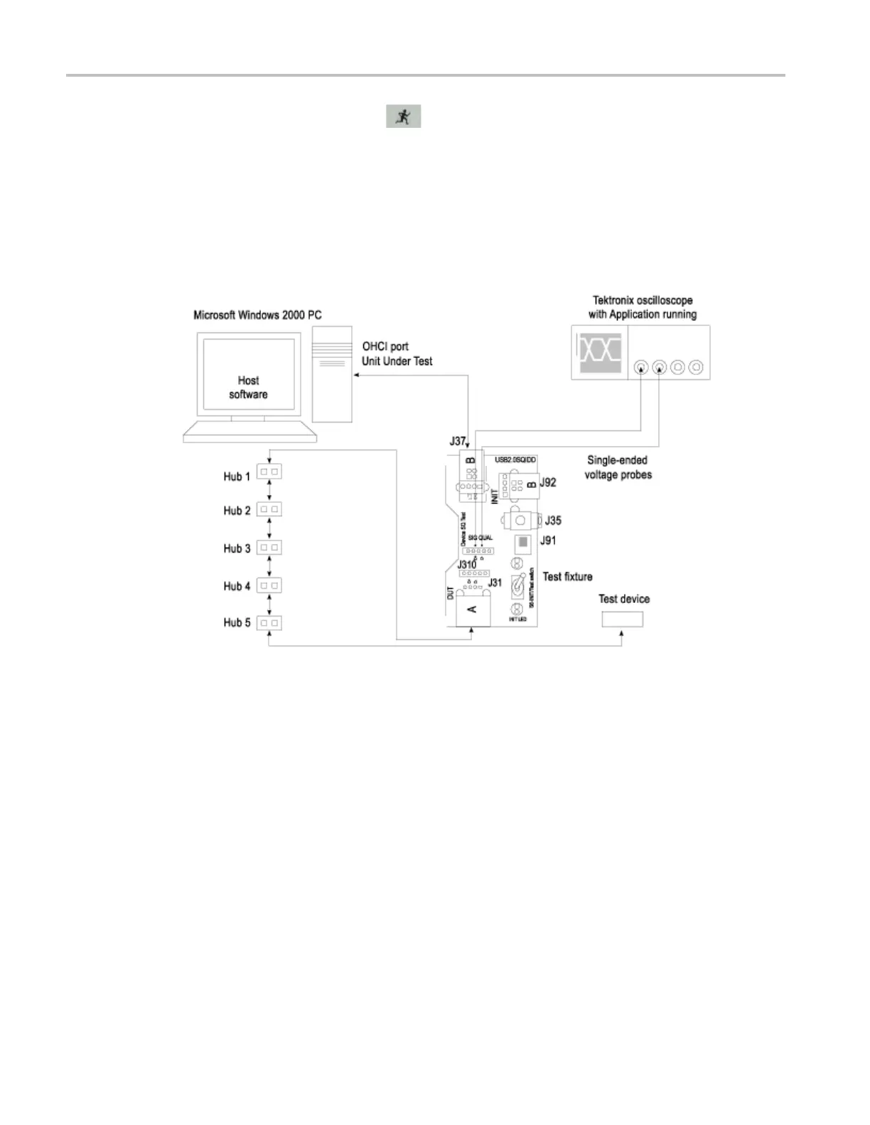
Full Speed Upstream Signal Quality Setup
To set up the equipment for Full Speed Upstream test, follow these steps:
1. Use the A receptacle to connect the USB unit unde r test (device) to the Inrush section of the test fixture.
2. Connect the Qualifier device to the Adjacent Trigger and Droop section of the test fixture as shown in
the next figure.
3. Connect Ch1 of the D+ probe to the D+ pins on the Inrush section of the test fixture.
4. Connect Ch2 of the D– p robe to the D– pins on the Inrush section of the test fixture.
5. Connect the D+ (D– for Low speed) pin of the Adjacent Trigger and Droop Section of the test fixture
to Ch3 as s hown in the next figure.
194 TDSUSB2 Universal Serial Bus Measurements Package