Operating Basics Configure Limits
See Also
Configuring Signal Quality Measurements
Configuring Inrush Current Measurements
Configuring Droop Measurements
Configuring
Receiver Sensitivity Measurements
Configuring Chirp Measurement
Configure Limits
The application displays the maximum and minimum values for the selected tests. You can use the ‘>’ sign
on the keypad to configure limits for these options.
Option
Description
Set Sets the values you enter
Default Restore the default values
Cancel Cancels all the changes you enter
xxx
NOTE. The application enables the Confi gure Limits values when you select the option File> Preferences>
Advanced menu.
Configuring Signal Quality Measurements
To access the Measurement: Configure, go to Measurements> Configure. Be sure to select the relevant
measurements before you configure them. There are two tabs for the Signal Quality Measurements:
Configure and Source.
The Configure tab allows you to select and set the Tier, Signal Direction and the Test Point options. You
must select the Tier (Tier 1 through 6), the direction of signal (Upstream or Downstream) and the Test
Point (Near End or Far End) at which the unit will be tested.
For Low Speed and High Speed signals, you can set Test Point to Near End or Far End. For Full Speed
signals, you can set the Test Point to Far End only.
For Monotonic Property measurement, you can configure the mea surement levels.
The Source tab allows you to select the Source of the signal: a live signal or the signal from a file. For a
live signal there are two options: Differential and Single-Ended. For Low Speed and Full Speed devices,
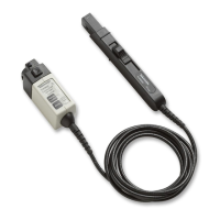
you can test only single-ended signals (D+ and D–). For High Speed devices, it is recommended that
you use a differential probe.
TDSUSB2 Universal Serial Bus Measurements Package 37