Page vii
EAR-Controlled Technology Subject to Restrictions Contained on the Cover Page.
WEEE ............................................................................................................................................................ 180
CE ................................................................................................................................................................. 180
Material Disclosure Table ............................................................................................................................. 181
LIST OF FIGURES
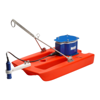
Figure 1. RiverRay/RiverPro/RioPro Boat Overview .................................................................................. 5
Figure 2. RiverPro/RioPro Connections – Bluetooth Connection .............................................................. 8
Figure 3. RiverPro/RioPro Serial Connection ........................................................................................... 11
Figure 4. Download Directory ................................................................................................................. 15
Figure 5. Recover Loop Recorder ............................................................................................................ 16
Figure 6. Mounting Plate Installation ...................................................................................................... 20
Figure 7. Removing the I/O Cable ........................................................................................................... 23
Figure 8. Do not use Zip-Ties Directly on Cables ..................................................................................... 25
Figure 9. RiverRay/RiverPro/RioPro I/O Cable Wiring ............................................................................. 26
Figure 10. Rio Grande I/O Cable Wiring .................................................................................................... 26
Figure 11. End-Cap User Mounting Holes ................................................................................................. 28
Figure 12. RiverPro Parts Location ............................................................................................................ 38
Figure 13. RioPro Parts Location ............................................................................................................... 39
Figure 14. I/O Cable Connector Lubrication .............................................................................................. 41
Figure 15. RiverPro/RioPro Compass Calibration Screen .......................................................................... 44
Figure 16. RiverPro/RioPro Compass Calibration Screen – Pitch/Roll ....................................................... 45
Figure 17. RiverPro Assembly .................................................................................................................... 47
Figure 18. RioPro Assembly ....................................................................................................................... 48
Figure 19. Testing the RiverPro/RioPro using WinRiver II ......................................................................... 56
Figure 20. Testing the RiverPro/RioPro using SxS Pro ............................................................................... 57
Figure 21. RiverRay/RiverPro/RioPro Boat Wiring Diagram ...................................................................... 64
Figure 22. 96B-6060 RiverPro Outline Installation Drawing ...................................................................... 75
Figure 23. 967-6150 RioPro 1200 kHz Outline Installation Drawing ......................................................... 76
Figure 24. Installing Feature Upgrades ..................................................................................................... 80
Figure 25. X, Y, and Z Velocities ............................................................................................................... 101
Figure 26. RiverPro/RioPro Coordinate Transformation ......................................................................... 102
Figure 27. RiverPro/RioPro Pitch and Roll ............................................................................................... 102
Figure 28. PD0 Standard Output Data Buffer Format ............................................................................. 137
Figure 29. Header Data Format ............................................................................................................... 138
Figure 30. Fixed Leader Data Format ...................................................................................................... 141
Figure 31. Variable Leader Data Format ................................................................................................. 146
Figure 32. Velocity Data Format .............................................................................................................. 149
Figure 33. Correlation Magnitude, Echo Intensity, Percent-Good, and Status Data Format................... 151
Figure 34. Bottom-Track Data Format..................................................................................................... 155
Figure 35. Surface Layer Leader Format .................................................................................................. 158
Figure 36. Surface Layer Velocity Format ................................................................................................ 159
Figure 37. Surface Data Correlation Magnitude, Echo Intensity, Percent-Good, and Status Data Format160
Figure 38. Automatic Mode Setup Data .................................................................................................. 165
Figure 39. Firmware Status Data ............................................................................................................. 167
Figure 40. Vertical Beam Range Format .................................................................................................. 168
Figure 41. Vertical Beam Profile Leader Format ..................................................................................... 169
Figure 42. Vertical Beam Profile Velocity Data Format ........................................................................... 171
Figure 43. Vertical Beam Profile Correlation Magnitude, Echo Intensity, Percent-Good, and Status Data Format
171
Figure 44. NMEA PD0 Data Message....................................................................................................... 173
Figure 45. Beam Correction Matrix Format ............................................................................................ 174
Figure 46. Reserved BIT Data Format ...................................................................................................... 175
Figure 47. Checksum Data Format .......................................................................................................... 175