. . . . .
ROUTINE MAINTENANCE
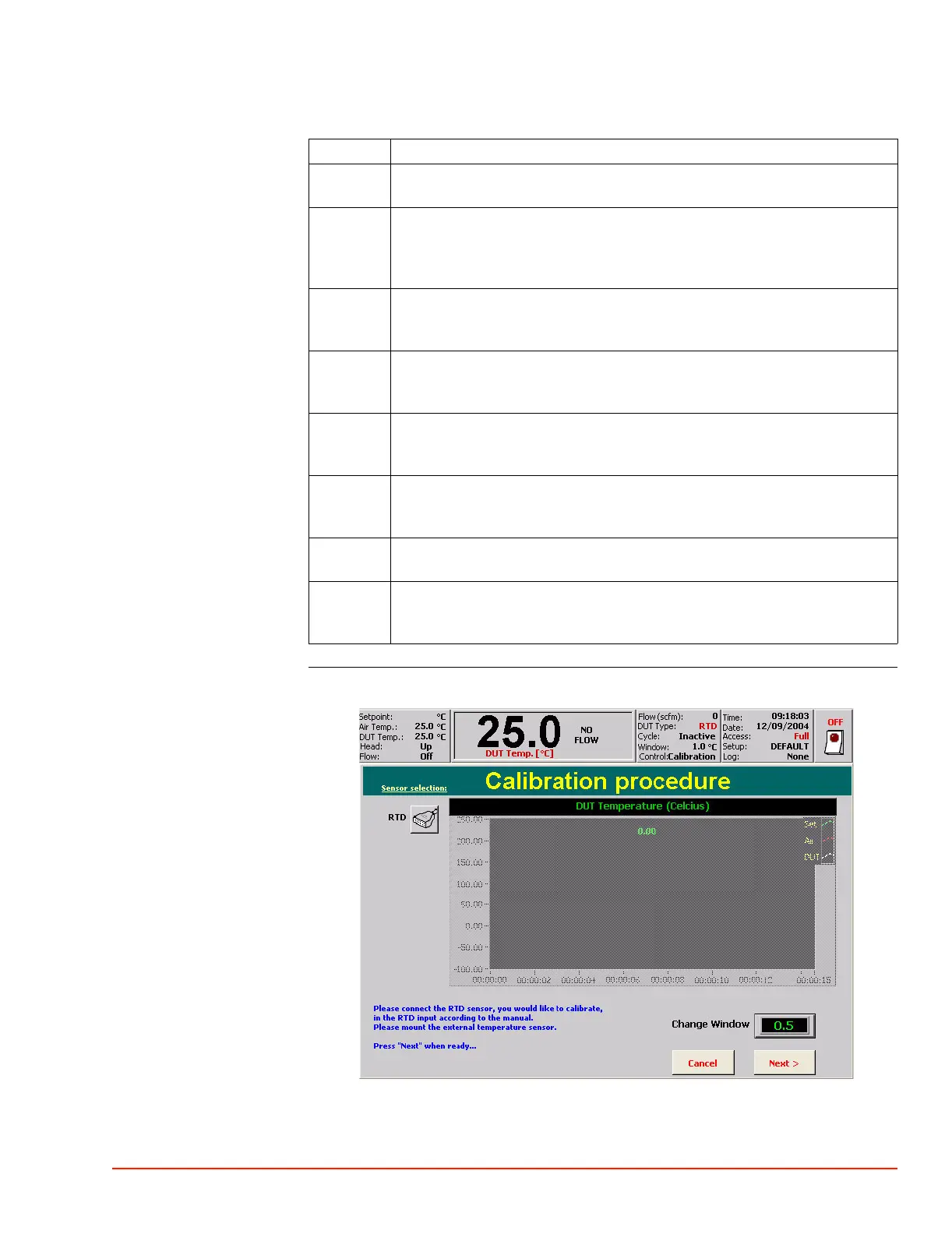
RTD Sensor Calibration (DUT Mode)
TP04300 Series Interface & Applications Manual 5-33
To calibrate an RTD sensor:
External Sensor
Method
(RTD Sensor)
1980_518.jpg
Step Action
1 Run system for half an hour at Ambient to stabilize components at normal
operating temperatures.
2 Toggle Head into Up position so System is not supplying main air flow
controlled to a setpoint (other than "Trickle" air flow).
NOTE: 4300B Systems should have the “Head: Lock” on. The “Head: Lock”
can be toggled on/off in the Utilities Screen.
3 Unplug any external RTD sensor plug from the RTD socket on the rear panel I/
O, and plug the Calibrator output plug into the RTD rear panel socket, taking
care to observe plug pin polarity.
4 Press the Utilities Screen tab, then press the "Sensor Calibration" button to
display Calibration Main Screen, then press "RTD’ to display the Calibrate
RTD Screen.
5 Set Calibrator output to the desired Low Calibration point (-60.0 °C), then press
"Next" to display Calibrate Low Temperature (RTD) Screen. Allow graph plot
to stabilize at low temperature.
6 Set Calibrator output to desired high Calibration point (+200.0 °C), then press
"Next" to display Calibrate High Temperature (RTD) Screen. Allow graph
plot to stabilize at high temperature.
7 Press "Next" to display Calibration Done (RTD) Screen, then press "Done" to
return to Utilities Screen.
8 Unplug the Calibrator output plug from the rear RTD socket, and replug the
external RTD sensor into the rear I/O socket, taking care to observe plug pin
polarity.
 Loading...