. . . . .
ROUTINE MAINTENANCE
High Temperature Verification
TP04300 Series Interface & Applications Manual 5-17
High Temperature Verification
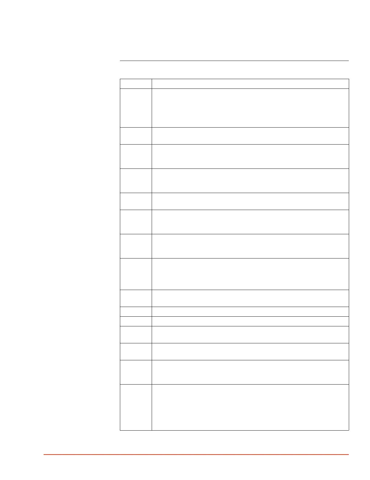
Procedure
Step Action
1 Access Setup Screen and
a) set "Air Temp Limit: High" at or above +200.0 °C, and
b) set "Air Temp Limit: Low" at or below -60.0 °C, and c) set "DUT Sensor
Type" to None (which enables main Air mode, measured by the Type T sensor
which is factory installed in the Head.
2 Run System for half an hour at Ambient to allow all components to stabilize at
normal operating temperatures before starting verification.
3 To verify main Air, use a) an external precision temperature Monitor, and b) a
T-type thermocouple cable in a “Y” configuration with 1- male, 1 female, and 1
Monitor connector
4 Access Utilities Screen to set "Flow: Off" so that the System is not supplying
air flow controlled to a setpoint (other than minimum constant "Trickle" air
flow).
5 To access the main Air T-type thermocouple plug, go to the back of the thermal
Head, and snap off the access cover, thereby exposing the plug and jack.
6 Carefully disconnect the main Air thermocouple to avoid bending the plug’s
two pins and gently pull the male plug out of the access opening. Disconnecting
this plug generates an "Error" prompt on the Statusbar (at top of screen).
7 Insert the main Air thermocouple plug which was just disconnected into the
female connector of the Monitor "Y" cable. Be aware of the plug’s pin polarity
(do not force the wide pin into the narrow slot).
8 Connect the Monitor "Y" cable male plug into the System female receptacle in
the Head, again taking care to match pin polarity. Connect the Monitor
connector on the "Y" cable into the Monitor. The Monitor is now connected in
series between the Head main Air T-type thermocouple and the System.
9 The Statusbar "Error" should clear; if System displays Error Screen, then press
"Clear Error" to exit the Error Screen.
10 From the Setup Screen make certain "DUT Sensor" is set to "None.”
11 Access Utilities Screen to set "Flow: On."
12 Then set the System temperature setpoint to +200.0 °C and allow System to run
until a stable AT TEMPERATURE is indicated within ±1 °C of setpoint.
13 Read the Monitor (not the System AT TEMPERATURE) and record the
Monitor value in the Low Temperature Verification (page 5-13).
14 If the difference between the Monitor and System readings is greater than ±1.0
°C, then recalibrate the System (see Calibration, page 5-20) after restoring the
System as follows.
15 To restore the System, access the Utilities Screen and set "Flow: Off" which
prevents running to a Setpoint; next disconnect the Monitor “Y” cable
connectors, which generates an "Error" prompt on the Statusbar (at top of
screen); reconnect the main Air thermocouple plug into the System female
receptacle; the Statusbar "Error" will clear; access Utilities Screen to set "Flow:
On."

 Loading...