5
ROUTINE MAINTENANCE
High Temperature Verification
5-18 TP04300 Series Interface & Applications Manual
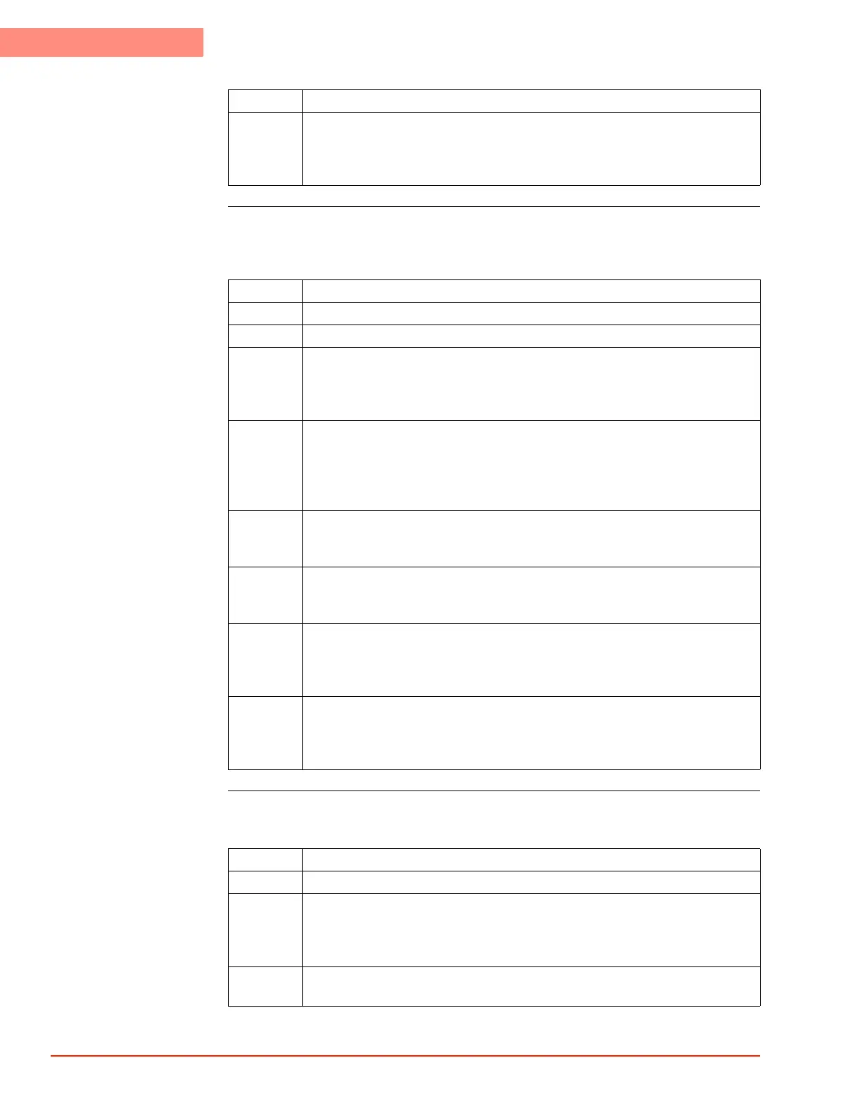
Verify DUT “T” or
“K” Modes (High
Temp.)
Verify DUT “RTD”
(High Temp.)
16 If the difference between the Monitor and System readings is between (within
the range of) ±1.0 °C, then no re-calibration is required. Restore the System as
given above (or continue High Temperature verification with the DUT Modes
(T, K, RTD, Diode sensors) below.
Step Action
Step Action
17 Access the Utilities Screen and set "Flow" to Off.
18 Set the external precision temperature Monitor output to +200.0 °C.
19 Insert the Monitor male plug into the appropriate sensor port on the System’s
rear I/O Panel: if verifying DUT T sensor, then choose the “DUT T” port; if
verifying DUT K sensor, then choose “DUT K” port. Be aware of plug pin
polarity (do not force the wide pin into the narrow opening).
20 Access the Setup Screen and
a) set "DUT Sensor" to "T-Type" or "K-Type," and
b) note that the System defaults to "DUT Mode: Air." If System was preset to
"DUT Mode: DUT," then be certain to reset "DUT Mode: Air" to prevent
heater damage.
21 This is NOT doing a DUT Mode test setup, where the DUT controls
temperature: it is a DUT sensor Verification setup, which procedure will be
driven by the Monitor output, interfaced as given above.
22 Allow the System temperature to stabilize, read the DUT temperature displayed
on the System, and record the System DUT temperature in theLow
Temperature Verification, page 5-13.
23 Compare the Monitor temperature setpoint value to the System displayed DUT
temperature. If the difference between the Monitor and System DUT values
is greater than +200.0 ±1.0 °C, then recalibrate the System (see Calibration,
page 5-20)
24 You may repeat the procedure for the other sensor type, or verify DUT RTD or
Diode, or proceed to verify Type T, or Type K, Low temperature or restore the
System by disconnecting the temperature Monitor from the System rear I/O
panel, and accessing Utilities Screen to set "Flow: On."
Step Action
25 Access the Utilities Screen and set "Flow" to Off.
26 Use an external Resistance Temperature Detector (RTD) Simulator (or use a
decade resistance box) accurate to .01% of setting, with a range from 10Ω to
1,111.110Ω, as the input to the System, rather than allowing the DUT to
control the System, as follows; for RTD connector wiring.
27 Set the RTD Simulator output for 175.840Ω (which is +200.0 °C on the
System).
 Loading...