. . . . .
PREPARATION FOR USE
TP04300 Series Interface & Applications Manual 2-15
Section E:
. . . . . . . . . . . . . . . . . . . . . . . . . . . . . . . . . . .
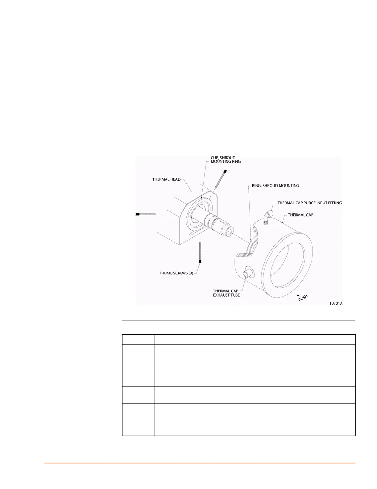
Attaching the Thermal Cap and Shroud
Introduction Each system is configured to customer specifications at the time of order and shipped
complete. Typically, the required assembling is to attach the thermal cap to the head module.
To attach the standard, transparent thermal cap onto the bottom of the head module, no
tools are required. Note that the same procedure applies for the optional, non-transparent
thermal cap.
Thermal Cap
10301A.jpg
Procedure
Step Action
1 At initial installation of the TP04300A, install the three thumbscrews in the
mounting ring at the head output. Thumbscrews are packed with the thermal
cap in a separate box.
2 Apply upward pressure, twist back and forth, and slip (push) the thermal cap
into the mounting ring of the head module.
3 Rotate the thermal cap to locate its exhaust port away from the operator's
position, and tighten the three thumbscrews to secure the thermal cap in place.
4 Slip the thermal shroud over the end of the head outlet nozzle to concentrate the
air flow around the DUT. Five different shaped shrouds are provided. Use the
appropriate shaped one for the type of DUT being tested (additional sizes are
available from Temptronic).

 Loading...