. . . . .
ROUTINE MAINTENANCE
High Temperature Verification
TP04300 Series Interface & Applications Manual 5-19
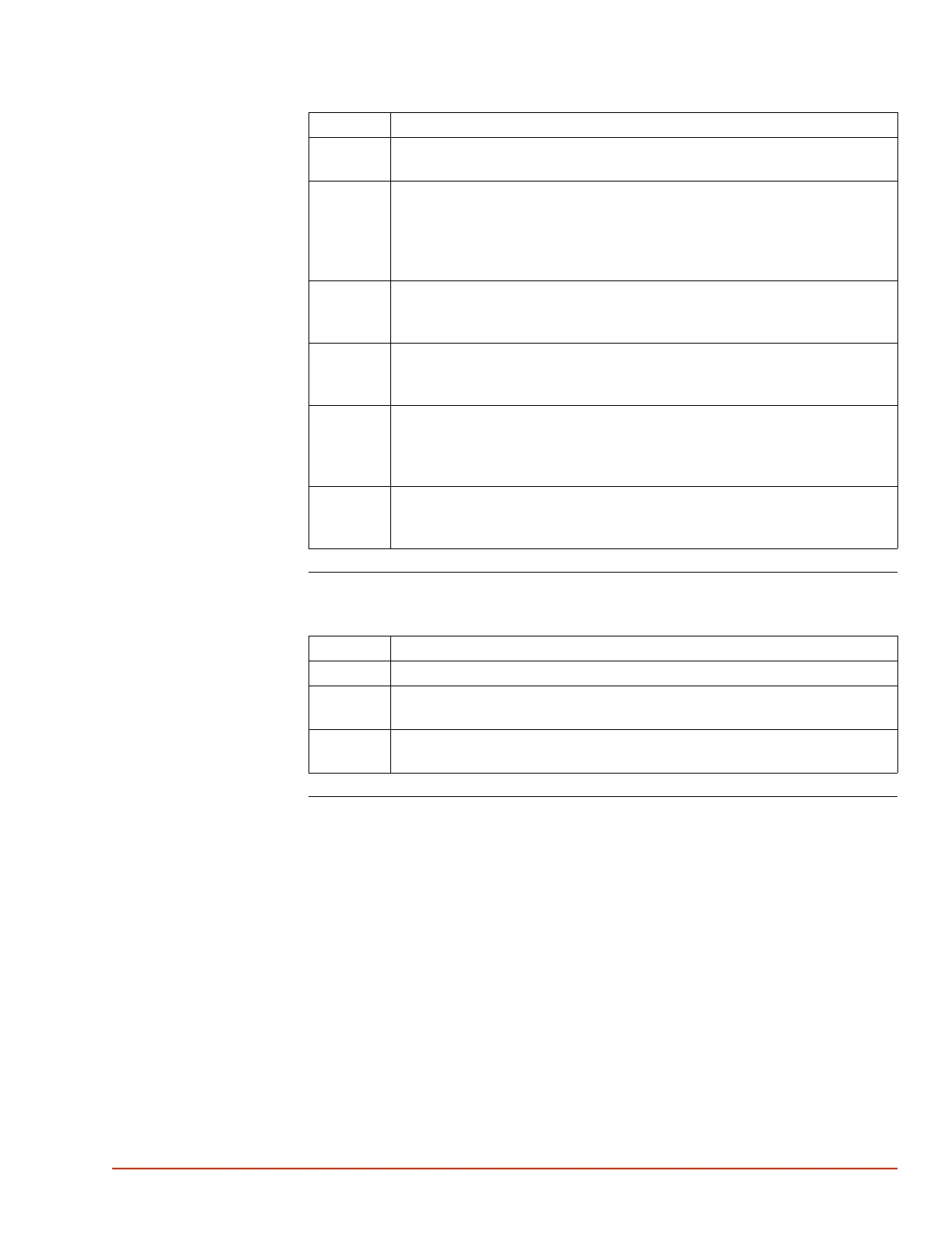
Verify DUT “Diode”
(High Temp.)
28 Insert the RTD Simulator male plug into the “DUT RTD/Diode” sensor port on
the System rear I/O panel.
29 Access the Setup Screen and
a) set "DUT Sensor" to "RTD," and
b) note that the System defaults to "DUT Mode: Air." If System was preset to
"DUT Mode: DUT," then be certain to reset "DUT Mode: Air" to prevent
heater damage.
30 This is NOT doing a DUT Mode test setup, where the DUT controls
temperature: it is a DUT sensor Verification setup, which procedure will be
driven by the RTD Simulator output, interfaced as given above.
31 Allow the System temperature to stabilize, read the DUT temperature displayed
on the System, and record the System DUT temperature in the Maintenance
Log, page 5-2.
32 Compare the RTD Simulator temperature setpoint value to the System
displayed DUT temperature. If the difference between the Simulator and
System DUT values is greater than +200.0 ±1.0 °C, then recalibrate the
System (see Calibration, page 5-20).
33 Proceed to verify Diode, below, or to Low Temperature verification or restore
the System by disconnecting the RTD Simulator from the System rear I/O
panel, and accessing Utilities Screen to set "Flow: On.
Step Action
Step Action
34 To verify a Diode sensor, first calibrate the Diode (see Calibration, page 5-20).
35 After calibrating the Diode, then an external Type T or Type K sensor may be
interfaced to the Diode and can be read to verify the calibration.
36 Temperature accuracy (the acceptable temperature range above/below setpoint)
will vary based on the chosen Diode’s linearity.
 Loading...