2
PREPARATION FOR USE
Configuring the Auto-Transformer Wires
2-24 TP04300 Series Interface & Applications Manual
Wiring for Input
Voltage of 215V to
224V:
Wiring for Input
Voltage of 225V to
234V:
Procedure:
Wire Marker # Wire Color From To
104 Brown TB4-2 TB27-2
107 Brown TB1-2 TB25-2
Wire Marker # Wire Color From To
104 Brown TB4-2 TB27-2
107 Brown TB1-2 TB26-2
Step Action
1 Make a note of the facility’s Input Line Voltage. For detail, see To Measure
Input Line Voltage, page 2-21).
1 Place the rear panel Circuit Breaker, CB1 in an Off (downward) position.
Unplug the Main Power Cord.
2 Remove the right side panel.
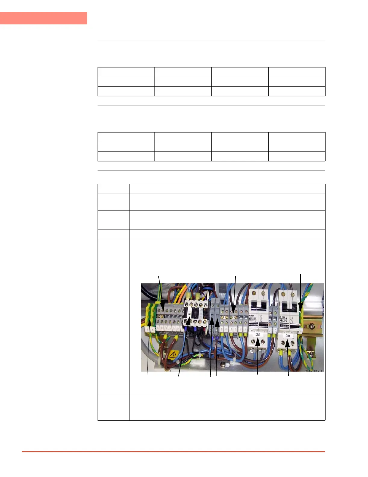
3 Access the slanted (High Voltage) DIN rail, located on bottom lower right, on
which are mounted Circuit Breakers CB5, CB4, and several wiring terminal
blocks.
LM01990_803.JPG
4 Use the Wiring Tables (above) to connect the wires to the appropriate terminal
blocks based on your Input Line Voltage.
5 Re-install panel in reverse order of dis-assembly.
GB2
CB4
CB5
F2
F1
K1
Terminal Blocks:
29, 28, 27, 26, 25, 24, 23
Terminal Blocks:
6, 5, 4, 3, 2, 1,
GB1
 Loading...