MISCELLANEOUS
4157082 First Edition 9-3
9
Wheel Hubs and Bearings
Removal
See Figures 9-4 and 9-5.
NOTE
The hub assemblies are unique to each side and are
marked “L” and “R.” Do not exchange them side-for-side.
1. Park the mower safely. (See “Park Mower Safely” on
page 1-6.)
2. Remove the transport wheels (if equipped). (See
“Transport Wheels (Optional)” on page 9-2.)
Figure 9-4
3. Remove lock nut (1) from the transport roller shaft.
Figure 9-5
4. Remove latching collar (4), bushing (3), and hub
assembly (2).
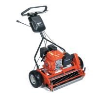
Disassembly
See Figure 9-6.
Figure 9-6
1. Remove washer (1), bushing (2), and clutch sleeve
(3) from hub (5).
2. Remove seals (4) and bearing (6).
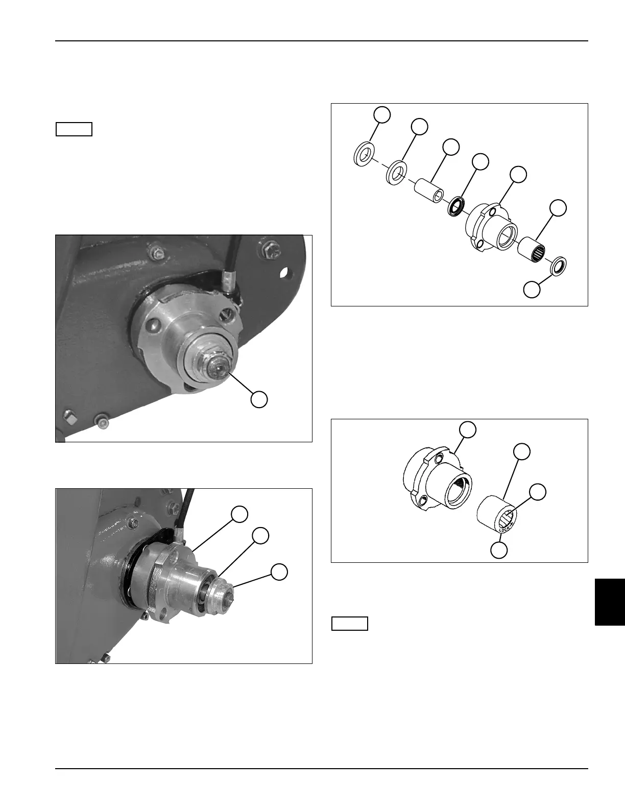
Assembly
See Figures 9-7 and 9-8.
Figure 9-7
1. Apply lithium grease NLGI Grade 2 to the wheel
bearing rollers (3).
NOTE
The bearing used in the wheel hub is directional and
must be installed in the correct direction of rotation.
2. Install bearing (2) in the hub (1):
Right Wheel Hub: Install the bearing with the word
“lock” and arrow (4) stamped in the face facing the
OUTSIDE of the hub housing.
Left Wheel Hub: Install the bearing with the word
“lock” and arrow (4) stamped in the face facing the
INSIDE of the hub housing.
1
TN0132
2
TN0051
3
4
1
TN0053
2
3
4
5
6
4
3
TN0054
1
2
4