HYDRAULIC DRIVE SYSTEM
6-34 36” & 40” Toro GrandStand Service Manual
6
23. Purge the air from the hydraulic system. See
“Bleeding the Hydraulic System” on page 6-35.
20. Lower the machine onto the ground.
21. Apply the parking brake.
22. Torquethewheellugnutsto85±8ft-lbs.(115±
10.8Nm)(Fig.543).
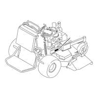
Fig. 542 DSCN-2805a
Fig. 543 DSCN-2880a
Subtracttherstreadingfromthesecondreadingand
determine if it is an acceptable GPM.
Example:
1stReading:300psi(21bar)reading7gpm(26l/m)
2ndReading:1100psi(76bar)reading3gpm(11l/m)
7 gpm (1st reading)
- 3 gpm (2nd reading)
4 gpm (the difference)
Refer to the Hydro-Gear pump service manual for
maximumacceptableowdroop,ordifference.
18. Afterallnecessaryrepairshavebeenmade,re-
connect the hydraulic hoses to the wheel motor
ttings.
19. Secure the tire assembly to the wheel motor hub
using the four wheel lug nuts (Fig. 542).
Note: The four wheel lug nuts will be torqued in a
later step.

 Loading...

