Technical data
OM 100.EPW 400.202002.en 25
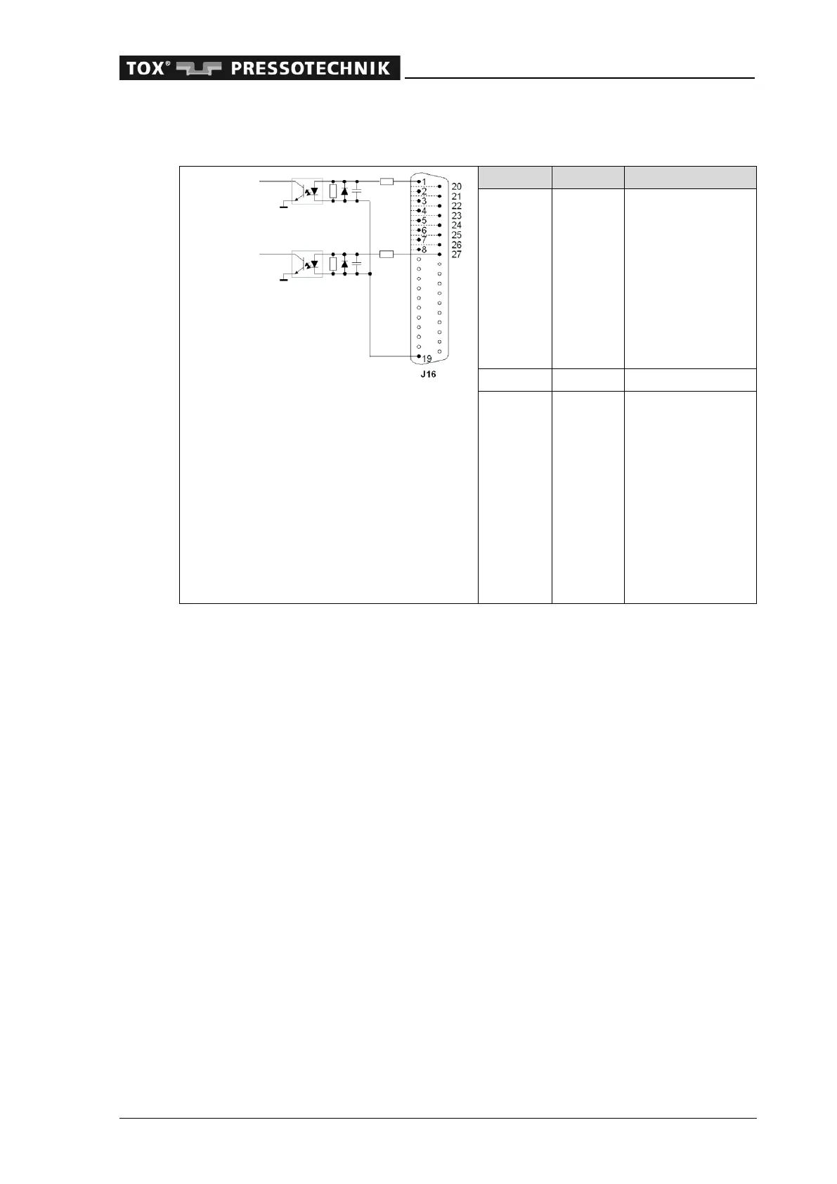
3.2.5 Built-in version: digital inputs I0 – I15 (37-pin connector)
1 I 0 Program bit 0
2 I 1 Program bit 1
3 I 2 Program bit 2
4 I 3 Program bit 3
5 I 4 Program bit 4
6 I 5 Program bit 5
7 I 6 Program strobe
8 I 7 Offset external
19 0 V 0 V external
20 I 8 Start measure-
ment
21 I 9 Reserve
22 I 10 Control panel in-
terlock
23 I 11 Error reset
24 I 12 Reserve
25 I 13 Configurable input
26 I 14 Access level bit 1
27 I 15 Reserve
On devices with field bus interface, the outputs, such as "Ready for operation", are
written on both the digital outputs and the field bus outputs. Whether the inputs are
read on the digital inputs or on the field bus inputs is determined in menu 'Additional-
>Communication parameters->Anybus-S Subprint'.
 Loading...