Technical data
28 OM 100.EPW400.202002.en
When connecting the DMS using the 4-conductor technique, pins 6 and 7 and pins 8
and 9 are bridged.
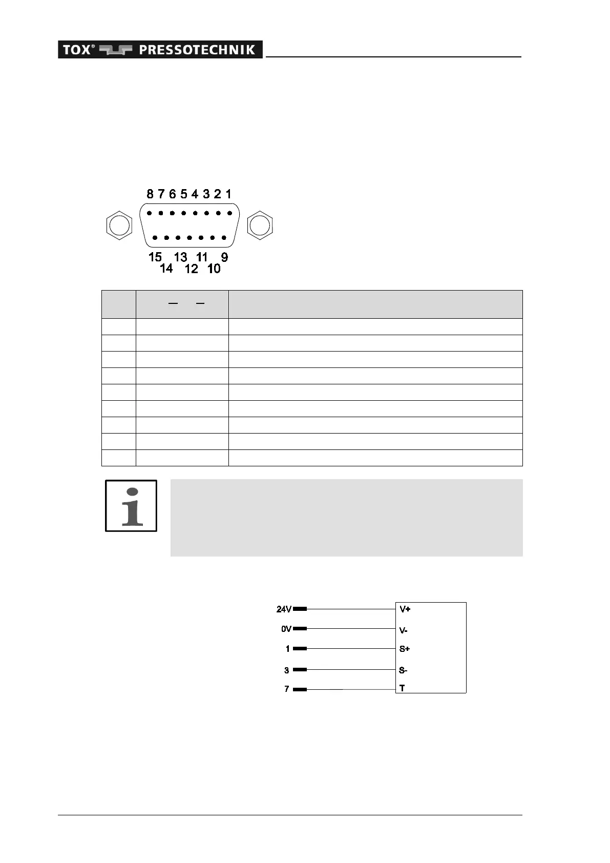
3.2.8 Built-in version: pin assignment, analog signals (channel Y force / channel X
distance) for analog standard signals
15-pin D-sub female connector (designation analog I/O)
put
1 i Force signal 0 - 10 V channel Y /1
3 i Ground, force signal channel Y /1
4 i Travel signal 0 - 10 V channel X /2
6 i Ground, travel signal channel X /2
7 o Analog output 1: tare +10 V / force / distance
2
8 o Ground
13 o Analog output 2: 0 - 10 V process-bound / force / distance
2
14 o Ground
15 o +10 V sensor supply
Note
For hardware model EPW 400.022.0X (2-channel) the second ana-
log input card is installed for channel pair 2 X/Y!
The connections are occupied the same as for the first card.
Channel Y force transducer, analog
Connection example of sensor with standard signal 0 - 10 V (ZKN with tare)
nector, analog I/O
2
Output function configurable